Features
Detect, review, and manage geometric holes, fillets, flanges, and logos.
HyperWorks supports the detection and management of geometric holes (2D and 3D), fillets, flanges, and logos, as well as mesh holes and flanges. After a feature is detected, it will keep track of the geometry or elements defining it and automatically update if their topology is modified by another operation, like splitting the edges or surfaces defining it.
Create Features
Use the Features tool to find and create geometric features in the displayed model.
-
From the Assembly ribbon, click the
Features tool.

Figure 1.If there are no Features in your model yet, the Feature Recognition Parameters dialog opens. -
Click Find to begin the detection process.
Tip: Using larger tolerances will capture more features but will increase processing time.Once the detection process is completed, the Feature Manager table opens.
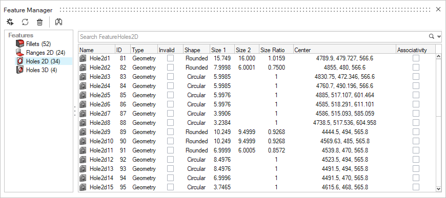
Figure 2. -
Use the Feature Manager to review and select the detected features.
By now, the feature entities are already in the model and can be also accessed via the Model Browser or by selecting them directly in the modeling window.
The Feature Manager uses the same search, filter, and sorting mechanisms as the Model Browser. The functions on the toolbar are:
 Rerun feature detection
- Return to the Feature Recognition Parameters dialog. Clicking Find in this dialog first clears all features in the model currently then re-detects them using the current parameters.
 Update
- Sync data and attributes for all, or individually selected features with their currently associated geometry or mesh.
 Delete all features
- Clears all features from the model. To remove individual features, select them anywhere and press Delete.
 Fit view to selected features
- Turn on to automatically fit the view to the features selected in the table.
- You can interact with features in the modeling window by setting the entity selector filter to Features with the mouse or by pressing the E key.
- Selection conversion between features and surfaces, lines, or elements (depending on feature type) is supported by switching the filter type with an active selection.
- Advanced selection methods are available for selecting features By Config, and geometry or mesh By Features.
Feature Types
HyperWorks supports the detection and management of the following feature types:
- Geometry
- 2D holes
- 3D holes
- Flanges
- Fillets
- Logos
- Mesh (FE)
- 2D holes
- 3D holes
- Flanges
- Both (Geometry + Mesh Associativity)
- 2D holes
- 3D holes
2D and 3D Holes

Figure 3.
The following shapes and measured dimensions are supported for 2D holes:
- Circular
-
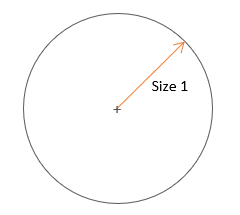
Figure 4. - Rounded
-

Figure 5. - Square
-

Figure 6. - Rectangular
-
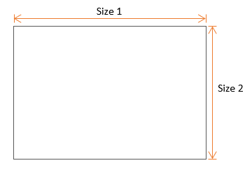
Figure 7. - General
-

Figure 8.
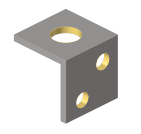
Figure 9.
- Defeature - Selected holes are defeatured using the same commands used by .
- Fill - Selected holes are filled with a filler surface using the same commands used by .
Flanges
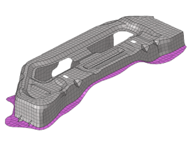
Figure 10.
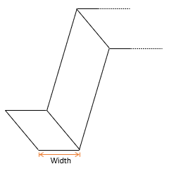
Figure 11.
Fillets
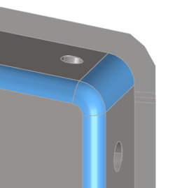
Figure 12.
Fillets can be curved rounds (exterior) or fillets (interior) connecting surface edges in place of a corner. Their measured dimensions are minimum and maximum radius, minimum and maximum width, and minimum and maximum angle.
- Defeature - Selected fillets are defeatured using the same commands used by .
Logos
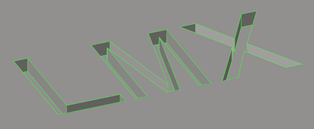
Figure 13.
Logos are collections of surfaces representing symbols or letters that are embossed, etched, or machined into other surfaces. Their measured dimensions are size and height.
- Defeature - Selected logos are defeatured using the same commands used by .