Move Patches and Merge Boundary Nodes
Use the Stitching tool to attach the various patches by moving patches and merging boundary nodes.
Each patch should have materials, properties and contacts assigned.
-
From the Airbag Solutions ribbon, click the
Stitching tool.

Figure 1. -
On the guide bar, click
 to define stitching
options.
to define stitching
options.
- Runtime: The final time for the pre-simulation that will be run for stitching the parts.
- T File: The sampling time for time history files.
- DT Animation: The sampling time for contour results.
- Noda/Cst: A parameter for controlling the time step.
- Folds Directory: The working directory for the pre-simulation run.
-
Set advanced selections as necessary by clicking
 on the guide bar.
-
Set advanced selections as necessary by clicking on the
guide bar.
The By Path option is the most convenient to use.
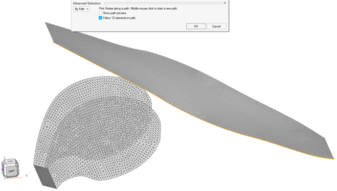
Figure 2. -
At the end of the pre-simulation run, click the satellite icon
 to load the new position of the
nodes.
The .h3d file is created. The file contains the new position of each node.
to load the new position of the
nodes.
The .h3d file is created. The file contains the new position of each node.