Built-In Library of Methods
By default, HyperMesh comes with a set of methods. These methods are always available even if you register your own custom methods.
- Rivet: JointLoad: Only supported for op2 and xdb
- Panel Metallic: Panel_FailureMode, Panel_ShearBuckling: Only supported for op2 and xdb
- Panel Composite: First Ply Failure: Supported for op2, h3d and xdb
- Beam: Stringer Axial Stress, Stringer Buckling, Stringer Axial Stress FBD, Stringer Buckling FBD: Only supported for op2 and xdb
JointLoad Method
You can chain another method which leverage data extracted from JointLoad to calculate a margin of safety.
- Rivet Diameter (held by the structural property)
- Material scale factor
- Metallic_D_scale: default to 4.0
- Composite_D_scale: default to 4.5
- User-defined scale factor (size_scale): default to 2.5
Box length=0.4*Size_scale*(D_scale*Diameter)
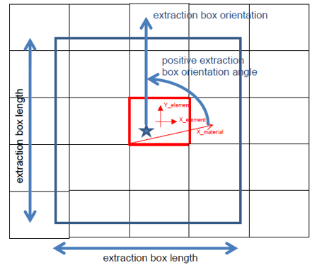
Figure 1.
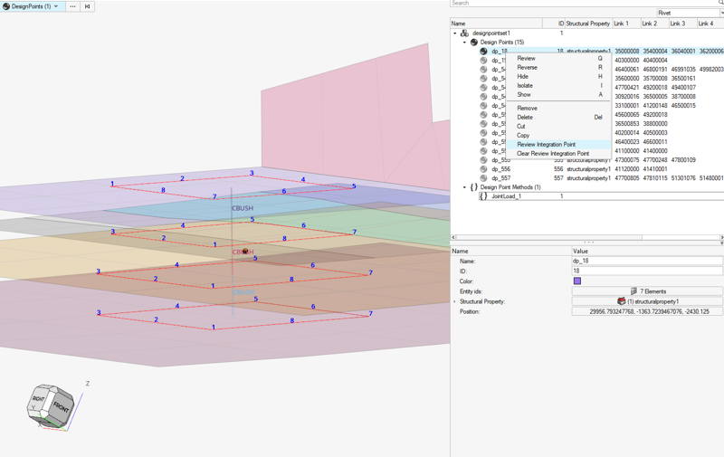
Figure 2. Review extraction areas per plate
The method has some parameters used for load extraction:
- BoxAngle
- Tilt the box counterclockwise by this angle about pierced shell material Z axis.
- Composite_D_scale, Metallic_D_scale, size_scale
- Used to define box length.
- IntPointSizePerEdge
- Defines the number of integration points along each box edge.
- Tension_shell_material_system
-
- 0: Rivet Max tension is extracted from raw 1D axial force Fx (default)
- 1: Rivet Max tension is extracted from Z component in shell’s material system
- DLS_calculations
-
- 1: compute DLS Ratios
- 0: do not evaluate DLS Ratios
First Ply Failure Method
The Panel_composite config comes with a set of various composite laminates first ply failure criteria. All of these failure criteria are bundled in a single certification method called “First_Ply_Failure”. This method internally invokes former ESACOMP engine.
Despite the method being available under the Panel_composite config, it evaluates failure criteria per element basis. As mentioned before, if the structural property assigned to a given designpoint refers to a user-defined property (PCOMP or PCOMPG), then all attributes required by the method are queried from this property. Otherwise, it will go directly per element’s property (supports PCOMP, PCOMPG, PCOMPP properties and MAT1, MAT8 cards).
All composite stresses are recalculated from shell element forces and moments based on the reference laminate property used. It then requires that result files contain shell element resultant forces and moments.
Math

Figure 3. Required allowable per criteria
+ Max stress for isotropic material requires Xt, Xc and S and considers out-of-plane shear.
- R= Transverse_Shear_Allowable_S13
- Q= Transverse_Shear_Allowable_S23
- *E3
The bolded design criteria automatically considers out-of-plane shear stresses.
If R and Q (for MAT8) are defined, traditional in-plane criteria will also consider the out-of-plane shear.
Terminology
Reserve Factor is a measure of margin to the onset of failure. The effective load multiplied with the Reserve Factor gives the design margin. Thus, Reserve Factor values greater than one indicate a positive design margin and values less than one indicate a negative design margin. The values of Reserve Factors are always greater than zero. The term Factor of Safety is used with the Reserve Factor/Inverse Reserve Factor/Failure Index; this is determined as inv(Reserve Factor).
For linear criteria (max strain, max stress and max fiber stress), it is equal to the value of the failure function f.
Margin of Safety = Reserve Factor – 1.
Activate Failure Theories
Once the First_Ply_Failure method is added to a designpointset, you can edit it from the browser. First, you can select the result level (Element | Layer | Recovery plane), then the type of margin to evaluate.
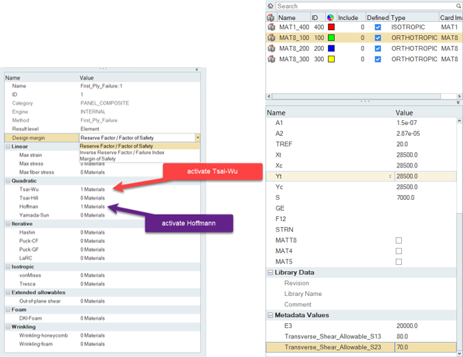
Figure 4. First ply failure selection & allowable as metadata
Example 1: Local Post-Processing

Figure 5.
Example 2: Global Post-Processing
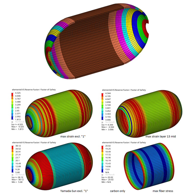
Figure 6.
First Ply Method References
- Mechanics of Composite Materials, Jones, R.M., Hemisphere, New York, 1975.
- Improved transverse shear stresses in composite finite elements based on first order shear deformation theory, R. Rolfes, K. Rohwer, International Journal for Numerical Methods in Engineering, 40:51–60, 1997.
- Failure criteria for an individual layer of a fiber reinforced composite laminate under in-plane loading. ESDU 83014, Amendment A. Engineering Sciences Data Unit, London, 1983/1986.
- Structural Materials Handbook, Volume 1 - Polymer Composites. ESA PSS-03-203, Issue 1. ESA Publications Division, ESTEC, Noordwijk, 1994.
- Introduction to Composite Materials. Technomic, Tsai, S.W. and Hahn, H.T., Westport, CT, 1980.
- Theory of Composite Design, Think Composites, Tsai, S.W., Dayton, OH, 1992.
- A Study of Failure Criteria of Fibrous Composite Materials, Paris F., George Washington University, Langley Research Center, Hampton, Virginia, NASA/CR-2001-210661.
- Failure Criteria for Unidirectional Fiber Composites, Hashin, Z., Journal of Applied Mechanics, 47 (1980), pp. 329-334.
- Failure criteria for non-metallic materials, Implementation of Puck´s failure criterion in ESAComp, FAIL-HPS-TN-003, European Agency Contract Report No. 16162/02/NL/CP, Braunschweig, 2004.
- Progressive failure analysis of advanced composites, Camanho P., NASA FA8655-06-1-3072, June 2009.
- Advanced Material Models for the Creep Behaviour of Polymer Hard Foams; Latest Advancements of Applied Composite Technology, Roth, M. A., Kraatz, A., Moneke, M., Kolupaev, V., Proceedings 2006 of the SAMPE Europe, 27th International Conference, Paris EXPO, Porte de Versailles, Paris, France, 27th - 29th March 2006. ISBN 3-99522677-2-4. pp. 253 - 2258.
- Manual for Structural Stability Analysis of Sandwich Plates and Shells, Sullins, R.T. et al, NASA CR-1457. 1969.
- A higher-order plate element for accurate prediction of interlaminar stresses in laminated composite plates, Ramesh S.S., Wang C.M., Reddy J.N. and Ang K.K., Composite Structures 91 (2009) 337–357.
Panel Metallic Failure
The Panel_metallic configuration is shipped with a DLL method called Panel_FailureMode. It computes four possible failure modes for a metallic panel. The method requires shell element forces to be available in the result file. It assumes a valid panel with constant thickness and retrieves thickness information from its structural property. Panel thickness is used to recompute element stress XX, YY, XY. Similarly, the structural property’s material is used to extract tensile/compressive and shear allowable. The method evaluates Margin of Safety as MS= Allowable/Stress -1 for the three directions. For directions one and two (XX and YY), depending on the stress state, either tensile or compressive allowable is used. For shear (XY) absolute stress value is considered in the margin of safety formula.
A fourth failure mode is computed as shear buckling failure of curved panel. In the latter, the highest shear force seen by all elements in the design point is considered. Shear buckling is a ratio of stress with Fscrit = 2KcE/(12*(1- 2)*(t/b)2 where Kc=Rs+0.2*W2/(R*T).
Rs is available as structural property metadata Radius_shear_constant and the default is 5.35.
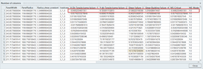
Figure 7. Panel Metallic Failure method
Beam Failures
- Stringer Axial Stress
- Stringer compressive buckling
The Stinger Axial Stress is a simple method which calculates the Compressive/Tensile margin of safety as:
MS= [(Compressive Stress limit)*(section Area)/(Axial Force)] -1; (resp. Tensile Stress limit)
In the case of freebody sections, Axial Force is mapped to the freebody resultant Fx.
- : average axial stress as (Axial Force)/(Section’s area)
- : material compressive stress limit
- K_constraint = “constraint coefficient” on structural property. Def=0.0699
- : beam section’s radius of gyration
- E: material young’s modulus