Contour Methods
Contour a single designpointset or designpointmethod. Method inputs and outputs are available to contour with aggregations.
-
From the Certification ribbon, click the Contour
tool.

Figure 1. -
Click
 on the guide bar to
proceed.
A dialog opens with options for creating contour or marker plots.
on the guide bar to
proceed.
A dialog opens with options for creating contour or marker plots. -
Define contour options.
-
Select a binding a data type.
Some methods can have results on elements, and some can have output only at the designpoint level.
If Entity Column is set to elementid, then the contour will be element-per-element.
If Entity Column is set to DDP, then if values are available per element on the designpoint, the Sorting key will apply. In turn, the min (max | absmin | absmax) value across elements will be retained and contoured on all elements of the relative designpoint.
Value Column lists all (float) inputs and outputs of a method valid for contour. The contour plot is based on this value. In the case of any sorting, it is used as a sorting metric.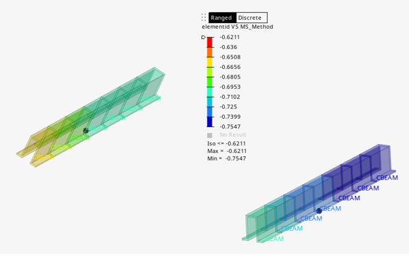 Figure 2. Contour per element
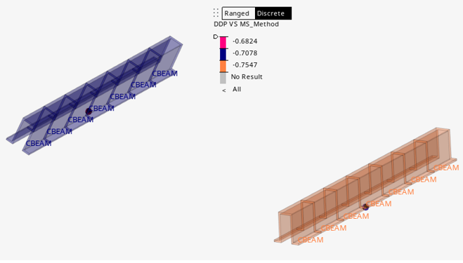 Figure 3. Contour aggregated to Structural Beam
-
Select a binding a data type.
-
Click the Marker tab to define markers options.
Markers can be created with or without a contour.
Selecting multiple options appends comma-separated values to the entity bind. In the case of a consolidated table, extra options for Method ID are available, which help to display the critical method on top of the margin of safety contour.
A shape can be added, which results in a sphere being placed on each entity defined in Entity Column. The shape can also be colored based on a separate legend defined by 3 ranges.
Restriction: There are sometimes scale issues with spheres on some models which result in spheres too small to be clearly seen.The same options available in the Contour tab are also available here. They control the markers and not the contour. Apply & Reset will apply change to markers only. Hence, it is possible to show a different marker value than the active contour.
Figure 4.