Box Trim Macro
Use the Box Trim utility to trim the model, or selected subset, along the global axis to fit the selected 3D box.
Trim Boxes
-
Edit the options in the dialog.
Table 1. Option Description Box trim type Determine how the selected model will be trimmed by selecting one of the following options from the pull-down menu: - left
- Split the model along global Y=ymiddle and save
the model between Y=ymin and Y= ymiddle (ymiddle
=(ymin+ymax)/2).
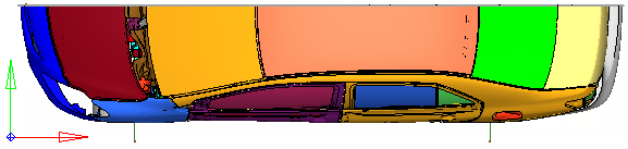
Figure 1. - right
- Split the model along global Y=ymiddle and save
the model between Y= ymiddle and Y=ymax.
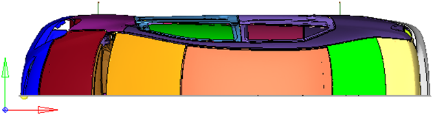
Figure 2. - front
- Split the model along global X=value (selected
value) and save the model between X=xmin and
X=value.
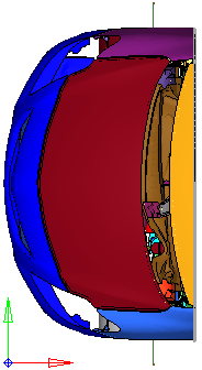
Figure 3. - rear
- Split the model along global X=value (selected
value) and save the model between X=value and
X=xmax.
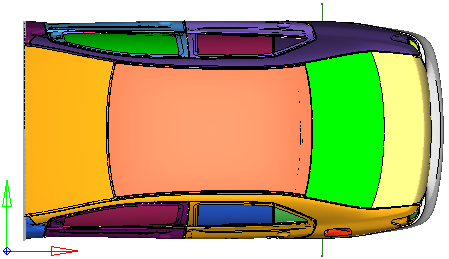
Figure 4. - frontleft
- Split the model along global Y=ymiddle and
X=value (selected value) and save the model
between Y=ymin and Y=ymiddle, and X=xmin and
X=value.
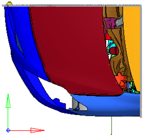
Figure 5. - frontright
- Split the model along global Y=0.0 and X=value
(selected value) and save the model between Y=0.0
and Y=ymax, and X=xmin and X=value.
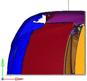
Figure 6. - rearleft
- Split the model along global Y=0.0 and X=value
(selected value), and save the model between
Y=ymin and Y=0.0, and X=value and X=xmax.
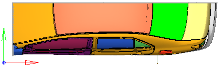
Figure 7. - rearright
- Split the model along global Y=0.0 and X=value
(selected value) and save the model between Y=0.0
and Y=ymax, and X=value and X=xmax.
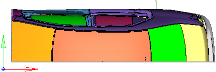
Figure 8. - custom
- Define the box by either selecting two corner nodes (Corners) or selecting the center node and dimensions (Distance from center).
X limit Define the trim location by selecting one of the following options: - By node
- Directs you to the Node Selection panel where you can select the node for the box trim location.
- By value
- Enter the value for the box trim location.
Defined by Define the trim location by selecting one of the following options: - Pick Corner Node
- Directs you to the Node Selection panel where you can select the two corner nodes that define the outer X, Y and Z bounds of the box.
- By Center Node
- Directs you to the Node Selection panel where you can select the center node, and then enter Delta X, Delta Y and Delta Z values which is the distance from the center node to the outer bounds of the box in global X, Y and Z directions.
Note: This option is only available when you select custom as the Box trim type.Create constraints Create Single Point Constraints (SPCs) for all of the nodes along the trimmed edges. When this option is activated, the following options are enabled: - SPC collector
- Specify a load collector to store the Single point constraint (SPC) created along the trimmed edge.
- Box collector
- Specify a box collector. A large hexa element that represents the box will be created for visualization in the specified collector.
Remesh options Enables access to additional options that help clean the trimmed edge elements in order to achieve a better mesh quality. Min size Defines the minimum size of remeshed elements on the trimmed edge. Element size can be defined by selecting one of the following options from the pull-down menu and entering a corresponding value in the elem size field. - relative
- Multiplier of the local element size
- absolute
- Actual element size
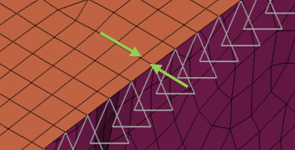
Figure 9. . Min size > 3 (absolute)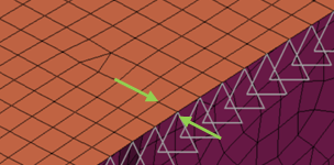
Figure 10. . Min size > 5 (absolute)Delete comps with Enables a filter to delete components after the trim. The components that are deleted after the trim can be defined by selecting one of the following options from the pull-down menu and entering a corresponding value. - num elems
- If the number of elements remaining after the box trim are lesser than specified value, then entire component will be deleted.
- % area
- Specify the percentage of the total area remaining after the trim. If the area after the trim is lesser than the specified value, then the component will be deleted.
Feature angle= This option is similar to the global feature angle specified in the mesh option. This value is used in element cleanup after the trim.