When you run the Convert to Special 2nd Order macro, a mesh matching is used to
remove the mid-side nodes at the shared edges between these first and second order
elements.
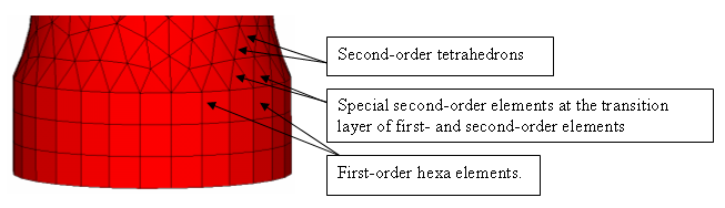
Models created for the ANSYS solver often contain
second-order pyramid and tetra elements in which most sides contain "mid-side
nodes". These types of elements exist in a transition layer between the first-order
hexa and second-order tetra elements, as shown below. Figure 1. Figure 2. Figure 3.
Beginning in HyperMesh 8.0, these types of elements are supported
and preserved in the model. HyperMesh can import:
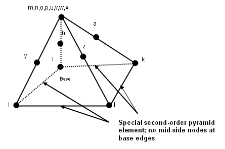
Pyramid-shaped SOLID95 and SOLID92 elements with side edges containing
mid-side nodes and bottom (base) edges that do not contain mid-side
nodes
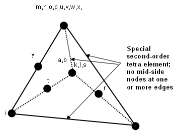
Tetrahedron elements with one or more edges that do not contain mid-side
nodes
SOLID95 (special type)
SOLID187 (special type)
These special elements will be imported as full second-order elements, including
mid-side nodes.
Imported full second-order elements are exported as special elements, thereby
restoring the original element configuration. Similarly, special second-order
elements created in HyperMesh are also exported as special
second-order elements.
Mesh the part for first-order with hexa or penta elements. Place these elements
in a collector with the correct element type (SOLID45).
Mesh the mating volume with second-order tetra elements. Place this mesh in a
separate component with the correct element type (SOLID95 or SOLID92).
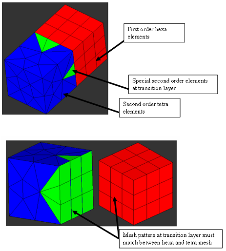
Ensure that the two mesh patterns have a common layer with shared edges
between.
From the ANSYS Tools page of the Utility menu, click the Convert to Special 2nd
Order macro.
Select the first-order component from the drop-down menu that shares a common
face with the second-order meshed component.
Select the second-order meshed component in the next drop-down menu and click
Apply.
The special order elements are generated
Export the file. Read it in the solver and check the elements.
The following images show examples of proper meshing for the above
practice. Figure 4.