Exercise 1: Create Joints
In this exercise, you will create a spherical joint and a revolute joint.
You can create joint definitions in the FE Joints panel, which can be accessed from the 1D page. HyperMesh supports the following standard joint types: spherical, revolute, cylindrical, planar, universal, translational, and locking. HyperMesh also supports LS-DYNA’s *CONSTRAINED_JOINT_STIFFNESS_OPTION property to define friction, damping, stop angles, and so on. The LS-DYNA solver interface supports the creation of joints in the FE Joints panel. The PAM-CRASH solver interface currently supports the creation of Joints as rod elements (see HM-4700: Using the PAM-CRASH Interface in HyperMesh).
A spherical joint consists of two coincident nodes. During analysis, the two coincident nodes are forced to remain coincident, but the bodies attached to each coincident node are allowed to rotate freely about the joint location.
Load the LS-DYNA Profile
In this step, you will load the LS-DYNA profile in HyperMesh.
-
Select OK to close the
User Profile dialog.
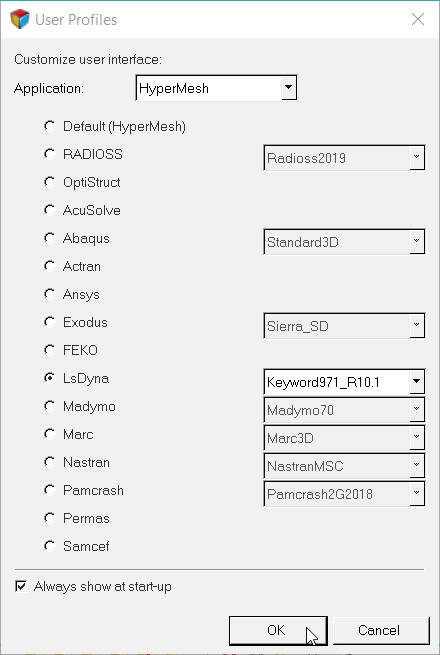
Figure 1.
Retrieve and View the Model File
In this step, you will open the model file and view it in HyperMesh.
-
Open a model file by completing one of the following options:
- Click from the menu bar.
- Click
 on the Standard
toolbar.
on the Standard
toolbar.
- In the Open Model dialog, open the joints.hm file.

Figure 2.
Activate Coincident Node Picking
In this step, you will activate coincident picking within the Graphics panel.
- Open the Graphics panel by clicking from the menu bar.
- Select the coincident picking checkbox.
- Click return.
Change the Display
In this step, you will change the display of the model in the graphics window by disabling components in the Model Browser.
-
Click
 next to each component except blue torus, orange torus, and New Joint to
disable the display of those elements.
next to each component except blue torus, orange torus, and New Joint to
disable the display of those elements.

Figure 3.

Figure 4.
Create a Spherical Joint
In this step, you will create a spherical joint using the Joints panel.
-
Use the node 1 selector to select a node in the center of both tori as
indicated in Figure 5.
The coincident node picking mechanism appears and displays two nodes, node 598 and node 1.
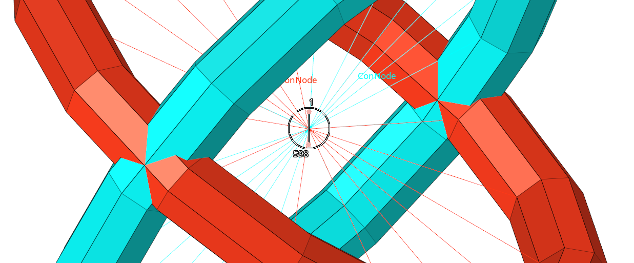
Figure 5. -
Select the node labeled 598.

Figure 6. -
Select the node labeled 1.

Figure 7. - From the the Joints panel, click create.

Change the Display
In this step, you will change the display of the model using the component folder of the Model Browser.

Figure 9.
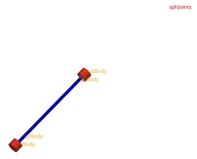 Figure 10.
 Create a Revolute Joint
In this step, you will create a revolute joint using the Joints panel.
-
Zoom in on one end of the shaft assembly as indicated in Figure 11.
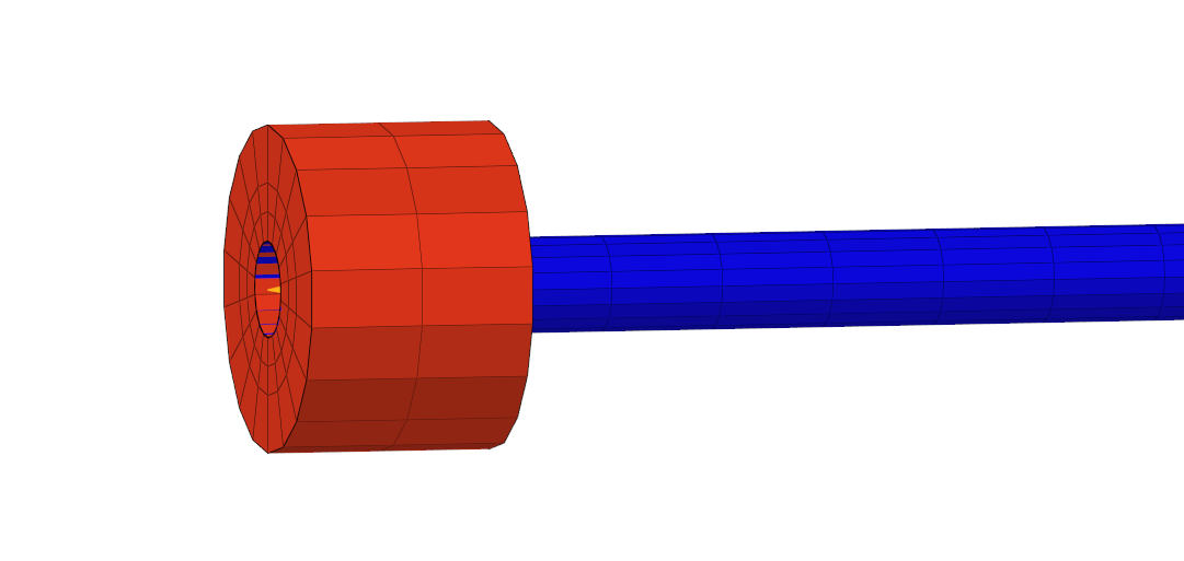
Figure 11. -
Using the node 1 selector, select a node at the center of one of the rigid link
elements.
The coincident node picking mechanism appears.

Figure 12. -
Using the node 3 selector, select a node at the center of the opposing pair of
blue and orange rigid link elements.
The coincident node picking mechanism appears.

Figure 13. -
Click create.

Figure 14.