In this tutorial, you will increase the diameter of one of the prongs of a yoke using
morph volumes. You will reflect the shape on to the other prong and finally position the
combined shapes from one yoke to the other.
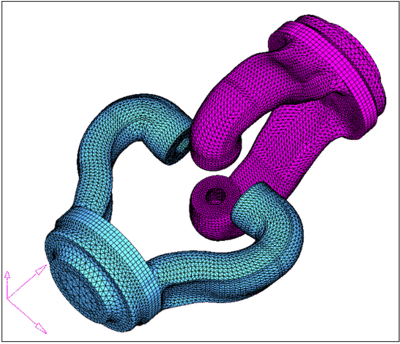
This exercise uses the yoke.hm file, which can be found in the
hm.zip file. Copy the file(s) from this directory to your
working directory. Figure 1.
Open the Model File
In this step you will open the model file, yoke.hm.
Open the model file, yoke.hm.
In the Model Browser, right-click the component
yoke_2 and select Hide. Make
sure component yoke_1 is in Show
mode.
Convert Hexas to Morph Volume
In this step you will convert hexas to morph volume.
From the menu bar, select Morphing > Create > Morph Volumes, then select the convert subpanel.
Select elems >> by collector.
Select hexas. Make sure that register all inner nodes is
checked.
Click select.
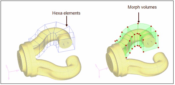
Click convert.
Figure 2.
Note: All seven hexa elements are converted into morph volumes.
Increase the Prong Diameter
In this step, you will increase the prong diameter.
In the Model Browser, right-click
Tag and select Show to display
all the tags.
From the menu bar, select Morphing > Morph, then select the move handles
subpanel.
Set the mode selector to move to node.
Click options and make sure morphing > mvols: is set to active (toggle if it is
set to inactive).
Click return.
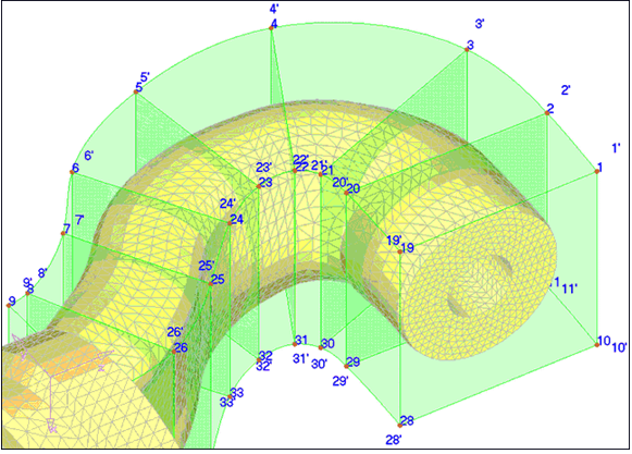
For handle, click Handle 1, and for node, click
tag 1'.
Repeat this process for the other 35 handles.
Figure 3.
Save the Morphed Shape
In this step, you will save the morphed shape.
From the menu bar, select Morphing > Create > Shapes.
Go to the save as shape subpanel.
For name=, type Prong1.
Toggle as handle perturbations to as node
perturbations.
Click create and select Yes to
the message that appears.
Click undo all to bring the model to its original
position before morphing.
Create a Coordinate System
In this step you will create a coordinate system.
You need to reference a coordinate system in order to create symmetry.
In the Model Browser, right-click and select
Hide for Shape and Morphing Volume.
Right-click on yoke_1 and select
Show.
Click origin and select the node labeled "origin."
For X-axis, select the node labeled "X."
For XY plane, select the node labeled "Y."
Click create.
Click return.
Create Symmetry
In this step, you will create symmetry.
From the menu bar, select Morphing > Create > Symmetries.
For name=, type symm1.
Under domains, click the checkbox for morph volumes
(make sure it is active).
Set 1 plane and keep the rest of the default
settings.
Click syst and select the newly created coordinate
system.
Click create.
Click return.
Position the Shapes
In this step, you will position the shapes of the two prongs of the yoke onto the
opposite yoke.
In the Model Browser, right-click
Title and select Show.
In the Model Browser, right-click
yoke_2 and click Show.
In the apply shapes subpanel, under shapes, change reflect shapes to
position shapes.
Change the selector from scale to no scale.
Click shapes and select the two shapes present in the
model.
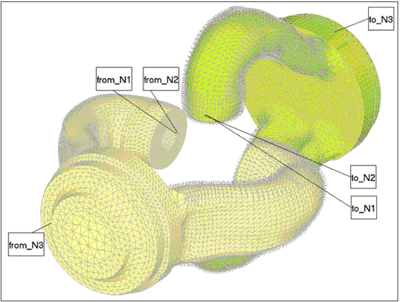
Under from: select the three nodes named from_N1,
from_N2, and from_N3 for
N1, N2, and
N3.
Under to: select the three nodes named to_N1,
to_N2, and to_N3 for
N1, N2, and
N3.
Click position.
Click return.
Figure 4.
Note: The two or more shapes have been created and applied to the other yoke.
The name of the first new shape (on the other yoke) will have a suffix “2”
because it is the second copy of the first shape and the second shape will
have a suffix of “11” as it is the first copy of the reflected shape.