Specify defaults for the spotweld check functionality of Model
Verification.
General Settings
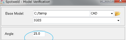
angle
Feature angle of the faces of FE.
Default/Allowed: 25 to 30 degrees
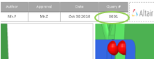
Slide-number
The starting number shown in the top corner of the PowerPoint file. Figure 1.
Default/Allowed: 1 to 10000
input
Initial directory for the Input file path.
Default/Allowed: C:/temp
output
Initial directory for the report output path.
Default/Allowed: C:/temp
action
User action type to be executed.
Check
Only intersection check will be executed, no reports.
Report
Only Reports will be generated from the previous check.
Both
Check and Report generation will be executed in a
sequence.
Default/Allowed: Check, Report or Both
mode
Default options for Run type.
interactive
Check executed in the front ground HyperMesh session
background
Check executed in the background HyperMesh
sessions. Automatic restart executed. If errors occur, the
errors will be displayed in the browser as "Crash"
keyword.
Default/Allowed: interactive or background
vip-format
Space or 8-digit separated format.
Default/Allowed: space or 8-digit
resolveconflictingpid
5 digits or 7 digits format correction.
Default/Allowed: ON or OFF
realize-check
Ignores failed spot welds during the check.
Default/Allowed: ON or OFF
allow-multiple-issues
All checks on all spot welds. There may be issues on the same
welds.
Default/Allowed: ON or OFF
extract-spot-cad
Converts CAD points/solids to the spot weld file. A copy of the spot
weld vip file will be stored in the CAD folder.
Default/Allowed: ON or OFF
extract-spot-cad-option
Converts point/solid entities to spot weld file.
Default/Allowed: points or solids
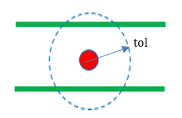
realize-tolerance (tol)
Allows searching the nearest spot on the same layer or different layer
or bot/all duplications. Figure 2.
Default/Allowed: 1.0 to 10.0
Closest
do-check
Turn OFF or ON the check
Default/Allowed: ON or OFF
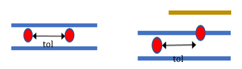
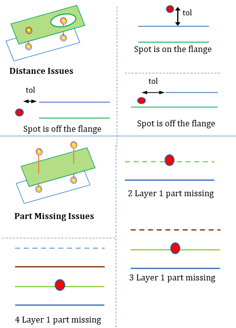
Tolerance (tol)
Distance between two spot welds less than/equal to this tolerance are
reported as duplicates. Distance is calculated after projecting to
normal direction. Figure 3.
Default/Allowed: 0.1 to 20.0
checktypes
Allows searching duplicate spot welds on the same layer (same weld
plates) or different layers or bots/all duplications.
Default/Allowed: sameStack, DifferentStack or Both
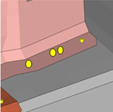
Spot weld found with the search radius of tolerance is identified. Figure 4.
Gap
do-check
Turn OFF or ON the check
Default/Allowed: ON or OFF
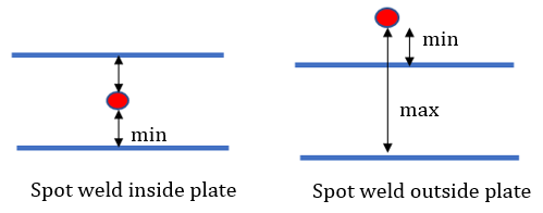
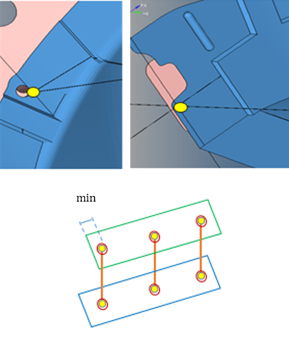
min
Minimum gap between Spot location and the weld plates. Figure 5.
Default/Allowed: 1.0 to 10.0
max
Maximum gap to be considered between Spot location and the weld plates.
This value is added to filter some spotwelds which are too far from the
model.
Default/Allowed: 10.0 to 100.0
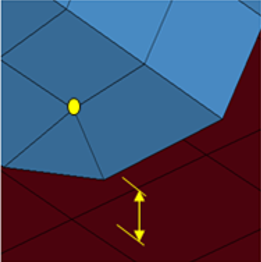
Spot weld between min and max distance from the nearest flange is identified,
perpendicular distance is checked. Figure 6.
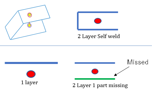
Single-Layer
do-check
Turn OFF or ON the check
Default/Allowed: ON or OFF
Self-welded spot welds are identified for reference. The link component 1 and link
component 2 is same. Figure 7.
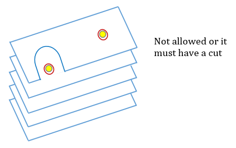
Multi-Layer
do-check
Turn OFF or ON the check
Default/Allowed: ON or OFF
threshold
Maximum allowed spot weld layers.
Default/Allowed: 2 to 4
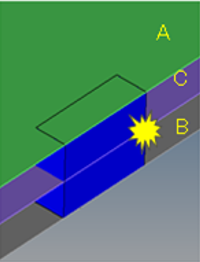
Spot welds that have layers more than the threshold value are identified for
reference. It is expected to have a notch to allow Spot gun. Figure 8.
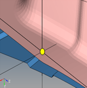
hm-issue
do-check
Turn OFF or ON the check
Default/Allowed: ON or OFF
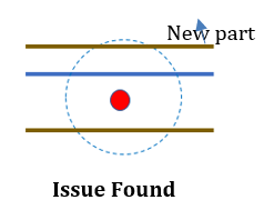
Spot welds that are far from the sheet metal part by “tolerance” search are
identified and part missing issues are directly identified by HyperMesh.
Tol
realize-tolerance (tol)
Figure 9.
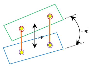
Parallel-flanges
do-check
Turn OFF or ON the check
Default/Allowed: ON or OFF
angle
Maximum angle between two plates at spot location. Figure 10.
Default/Allowed: 2.0 to 15.0
max-gap
Maximum physical gap between two plates at Spot location.
Default/Allowed: 1.0 to 5.0
Non-Parallel flanges are identified at Spot weld location. If the angle between two
sheet metal parts is more than the angle value and more than the gap value they are
identified. Figure 11.
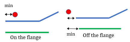
Incorrect-Location
do-check
Turn OFF or ON the check
Default/Allowed: ON or OFF
min-distance (min)
Minimum distance allowed from feature-line to the spot location. Figure 12.
Default/Allowed: 1.0 to 5.0
Issue is identified if the distance between Spot weld and the nearest feature edge is
more than the tolerance value. The tolerance refers to Spot gun “radius+gap”. Figure 13.
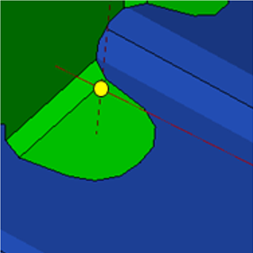
Few-Connections
do-check
Turn OFF or ON the check
Default/Allowed: ON or OFF
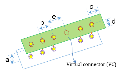
Proximity (a)
Search tolerance for realizing spot weld on the flanges, it is global
pitch.
Default/Allowed: 1.0 to 5.0 mm
pitch-spacing (b)
Average pitch distance for creating spot weld on flange.
Default/Allowed: 15.0 to 30.0
pitch-offset (c)
End offset distance on both side of the flange.
Default/Allowed: 5.0 to 8.0
pitch-edge-distance (d)
Offset distance from the edge of the flange.
Default/Allowed: 5.0 to 8.0
search tolerance (e)
Tolerance for searching Virtua connectors from existing connectors
created from the above parameter.
Default/Allowed: 30.0
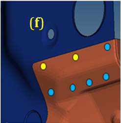
hole-diameter (f)
Search tolerance for finding nearest Bolt holes to avoid finding the
issue. Figure 14.
Default/Allowed: 4.0 to 40.0
Creating virtual spot (VS) welds with the above parameter. For every virtual
connector (VC) search nearest existing spot weld (blue) with “search tolerance”
value, identify location (yellow), if blue spot weld not found. Figure 15.
Flange-gap
do-check
Turn OFF or ON the check
Default/Allowed: ON or OFF
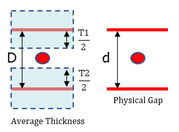
limit
+/- ratio of shortest gap between flanges at connector to average
component thickness value. It is also % of deviation. Figure 16.
Calculation : abs( D - d ) ≤ limit
Default/Allowed: 0.1 to 0.5 mm
This ratio of flange gap to average thickness of the component is compared with the
tolerance value. The issue is identified if the difference is the same or less than
the limit value.
Note: No Error will be reported if thickness does not exist or
offset is not done.
Figure 17.
Intersection
do-check
Turn OFF or ON the check
Default/Allowed: ON or OFF
spot-layers
Maximum number of layers considered for this check. Figure 18.
Default/Allowed: 2 to 3
Intersection on Spot realized FE data is found here or 2 layer to 3 layer or 3 layer
to 4 layer conversion possible welds are identified. Figure 19.
Fillets
Fillet identification angle
Figure 20.
do-check
Turn OFF or ON the check
Default/Allowed: ON or OFF
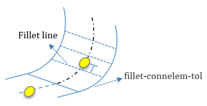
fillet-connelem-tol
Search tolerance for searching the nearest fillet edges to the
connector. Figure 21.
Default/Allowed: 10.0
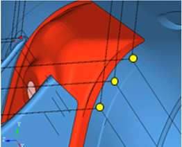
If Spot welds location less than the fillet-connelem-tol distance from the nearest
feature, line is identified here. Figure 22.
Reflect
do-check
Turn OFF or ON the check
Default/Allowed: ON or OFF
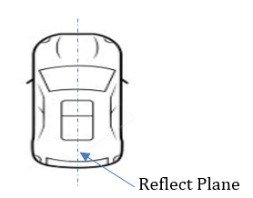
reflect-plane
Reflecting plane for the model which the spot welds are reflected and
checked again for realization. Figure 23.
Default/Allowed: zx
origin
Origin value. (for XY plane, origin is constant Z value)
Default/Allowed: 0 to 1000.0
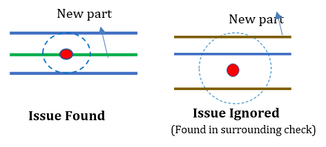
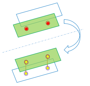
Failed spot welds are reflected at reflect-plane and re-realized, if successful in
realization, it is identified as an issue.
Issues will be ignored if surface offset is not executed and another spotweld exists
at the reflected location. Figure 24.
surrounding
do-check
Turn OFF or ON the check
Default/Allowed: ON or OFF
spot-layers
Maximum number of layers considered for this check. Figure 25.
Default/Allowed: 2 to 3
Intersection on Spot realized FE data is found here or 2 layer to 3 layer or 3 layer
to 4 layer conversion possible welds are identified. Figure 26.