I-Beam Analysis
Step through the model build process for a composite I-beam model.
- Ply creation
- Set ply normals
- Sublaminate creation
- Interface laminate creation
- Template property creation
- Surface geometry and mesh of I-beam
- Orthotropic material
- System collector that contains system used to assign material direction
- Unit system is PSI
- The manufacturing process uses complex tooling to manufacture 4 sublaminates
(co-cured to form the final part):
- top cap on Tool 1
- bottom cap on Tool 4
- left web on Tool 2
- right web on Tool 3
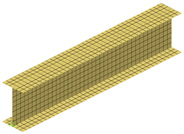
Figure 1.
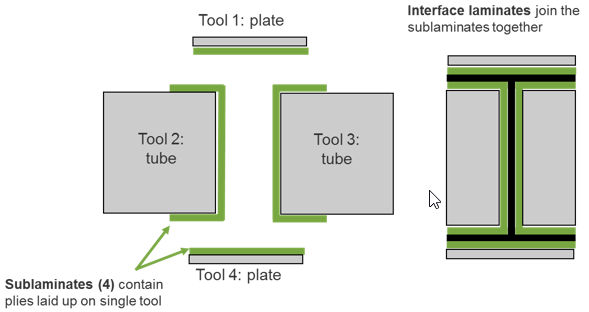
Figure 2.
Introduction
- Open HyperWorks.
- In the Solver Interface dialog, set the profile to OptiStruct.
- Open the model file, composite_beam.hm.
- Open the Composite Browser by clicking the Composite tool in the Model ribbon or .
Review Stacking Direction and Element Normals
Review stacking direction and element normals.
-
Toggle from color display to vector
display and click display. This will
display the current element normals for displayed 2D elements.
Note: For typical ply-based models with T junctions, cap element normals should point away from the web. Web element normals are arbitrary as long as the direction is consistent. Confirm that the element normals of the cap elements point away from the web and that web element normals point in the direction of global y.
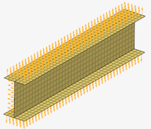
Figure 3.
Review Material Reference Orientation
Review the assigned material reference orientation.
-
Click review to plot the current material orientation.
The material orientation for this part has already been defined as the x
direction of the local system with id = 1.
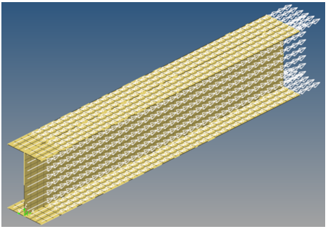
Figure 4.
Create Plies
Create the plies that make up the composite laminate.
-
After all plies are created, auto color by Shift-selecting the plies in the browser, selecting one the
Color icons, and clicking Auto
color.
Ply Name Ply ID Material Thickness Orientation Shape ply1 1 M40J 0.01 90 Top_cap ply2 2 M40J 0.01 0 Top_cap ply3 3 M40J 0.01 45 Left_web ply4 4 M40J 0.01 -45 Left_web ply5 5 M40J 0.01 90 Center_web ply6 6 M40J 0.01 45 Right_web ply7 7 M40J 0.01 -45 Right_web ply8 8 M40J 0.01 0 Bottom_cap ply9 9 M40J 0.01 90 Bottom_cap 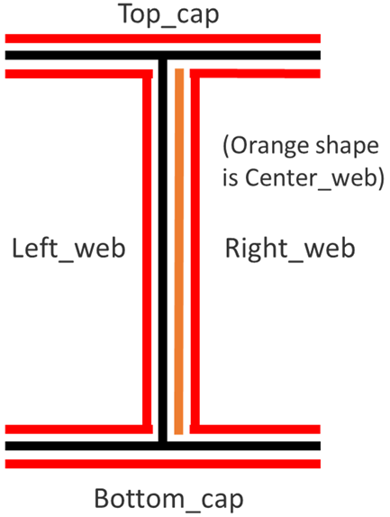 Figure 5.
Figure 6.
Set Ply Normals
Correct ply normals.
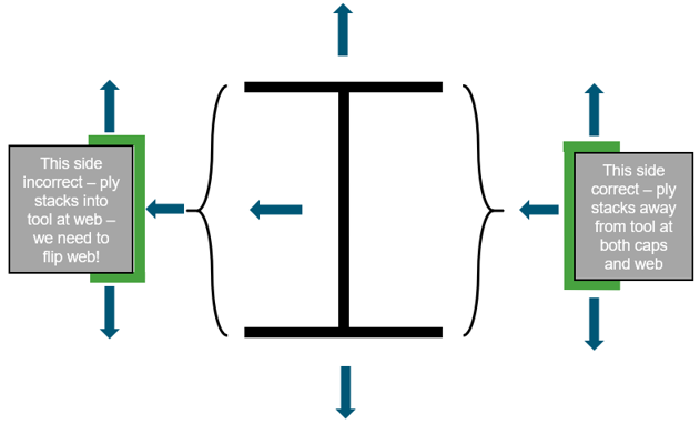
Figure 7.
- From the Composite Browser white space context menu, click .
- Toggle the Select ply arrows so that ply3 is active.
- Click Apply to plot current ply normals. Note the discontinuity described above.
- To correct ply normals, click the twice to access the element selection panel.
- Select only elements of the web and click proceed.
- Click the Reverse radio button under Normals and then click Apply. This will plot corrected ply normals for ply3.
- Reset the Display radio button under Normals to prevent any additional changes.
- Confirm the web of ply3 has no discontinuity with the caps by repeating Step 2 and Step 3.
- Repeat Step 3 through Step 8 for ply4.
Create Sublaminates
Create the sublaminates, which represent the stacks up plies on each unique tool used to manufacture the part.
-
Edit the names of the laminates and drag the plies from the unstacked plies
folder into the sublaminates so that they match the image below.
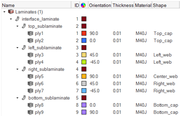 Figure 8.
Create the Interface
Define the interface, which specifies how the sublaminates are joined.
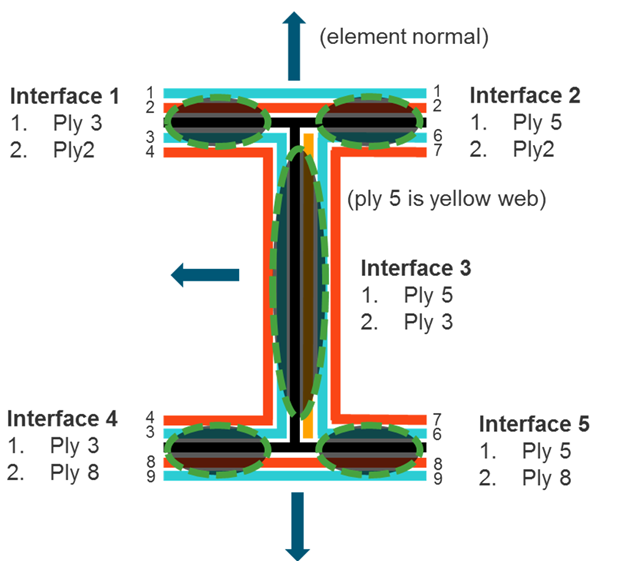
Figure 9.
-
Click OK to define the interfaces.
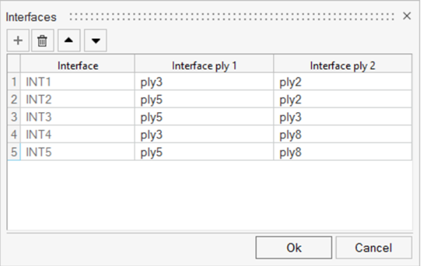
Figure 10.
Create Ply-Based Properties
Create ply-based template properties.
Typically, only one ply-based property is required per part. However, for cases where portions of a part require different property attributes (offset is most common), multiple properties are required. For the I-beam model, the elements that make up the web are at the midplane of the laminate, and the elements that make up the caps are at the tube tooling surfaces.
-
Assign the elements of the caps by right-clicking on the property in the
Model Browser and selecting
Assign from the context menu.
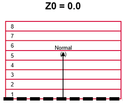
Figure 11. -
Repeat Step 1 through Step 5 for the web property. Set the name to
web. Leave Z0 as blank. This will place the midplane
of the laminate at the elements in the web.
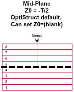
Figure 12.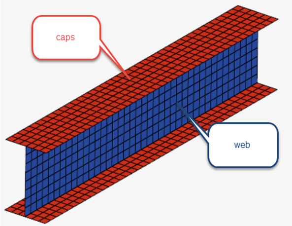
Figure 13.
Optional: Ply Direction Visualization
Plot vectors that represent the ply1 direction on each element.
-
Click the Ply 1 Direction option again to deactivate
it.
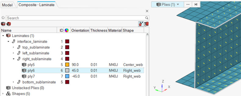
Figure 14.
Optional: Composite Layers Visualization
Visualize the thickness and ply layers of the laminate. This is used to confirm that all plies are in the expected order. If the interfaces were defined incorrectly, there will be discontinuities where portions of a ply jump to an unexpected location in the full stack.
-
In the Graphics area, type 5 in the ply visualization
thickness factor input. This will increase the displayed thickness of each ply
layer for the purposes of visualization.
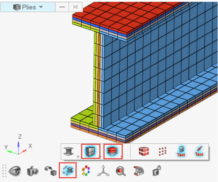 Figure 15.
 -
From the menu bar, select and type 5 in the ply visualization
thickness factor input. This will increase the displayed thickness of each ply
layer for the purposes of visualization.
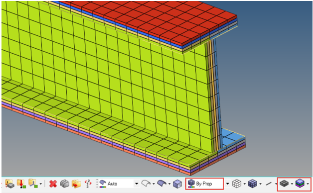
Figure 16.