Composite Analysis
Step through the composite model build process for a typical composite panel model.
- Setting stacking direction/element normals
- Material reference orientation
- Materials
- Ply creation
- Laminate creation
- Template property creation
- Visualization
- Result requests
- Tapered hat mesh and geometry
- Structure with combination of unidirectional carbon fiber and woven fiberglass plies
- Unit system of mmNS
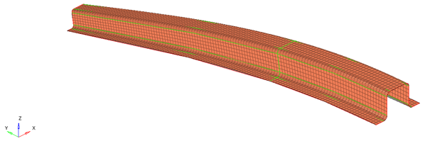
Figure 1.
Introduction
- Open HyperMesh Desktop.
- In the Solver Interface dialog, set the profile to OptiStruct.
- Open the model file, composite_hat.hm.
- Open the Composite Browser by clicking .
Define Stacking Direction
Define the stacking direction of plies in the laminate.
-
In the Composites panel, click reverse to flip the
direction of the element normals.
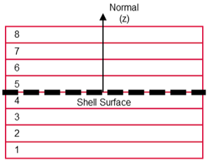
Figure 2.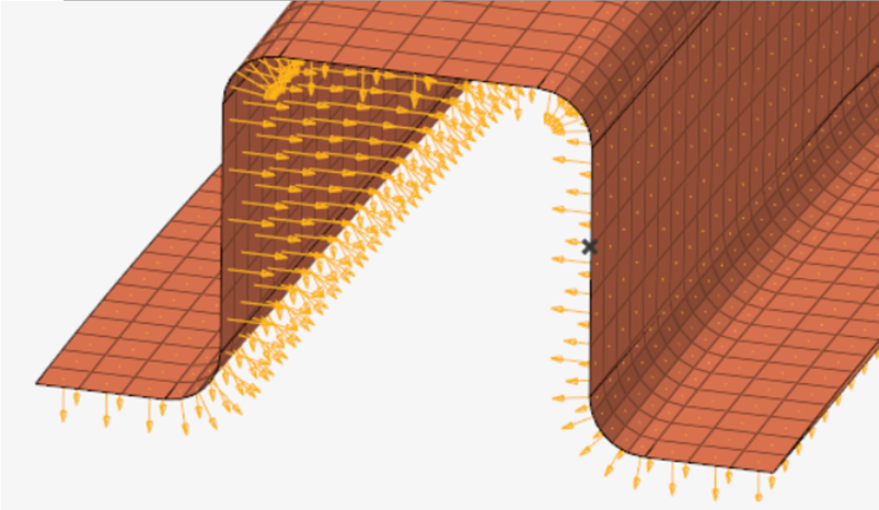
Figure 3.
Material Orientation
Define the material orientation for the part.
-
Select system id = 1, the local system on the geometry
near global (-3,0,40).
Note: The user profile and orientation method will determine the final solver cards created or manipulated. In this case specifically, in OptiStruct the MCID field of the element cards will be populated by the system id. Internally, OptiStruct will project the system x axis onto the elements to define the material x direction.Note: The composites panel can be used to project vectors or systems which define a material orientation. To set a material orientation which follows a curve, the Material Orientation tool can be used from the Composite Browser. Access this tool from white space by clicking .
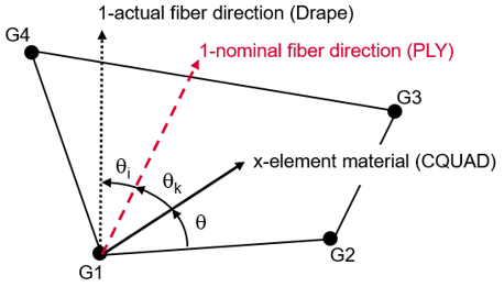
Figure 4.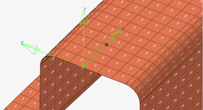
Figure 5.
Material Creation
Review materials.
-
Repeat Steps 1 and 2 for the material glass_epoxy.
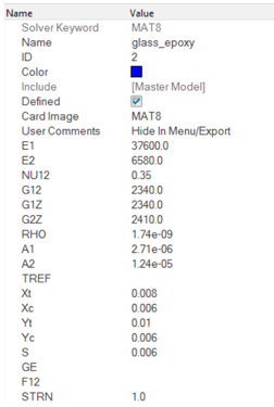
Figure 6.
Ply-Based Modeling
Overview of ply-based modeling.
- Plies – one unique HyperMesh ply per physical ply should be defined. Plies primarily define material, thickness, orientation and shape.
- Laminate – one HyperMesh laminate per physical part. The laminate defines the list of plies which make up the composite part.
- Template property – defines the data which traditional solver properties usually contain. Example attributes are offset and non structural mass. OptiStruct supports ply-based modeling entities, the specific ply-based property card is a PCOMPP. For other solvers, the template property takes the card image of the typical composite zone property and defines all solver property data other than layers. There should be one template property per unique combination of solver attributes.
Ply Creation
Create the plies that make up the composite laminate.
-
To define Shape1 and Shape 2:
-
Repeat Step 2 though 3d to create the other shape.
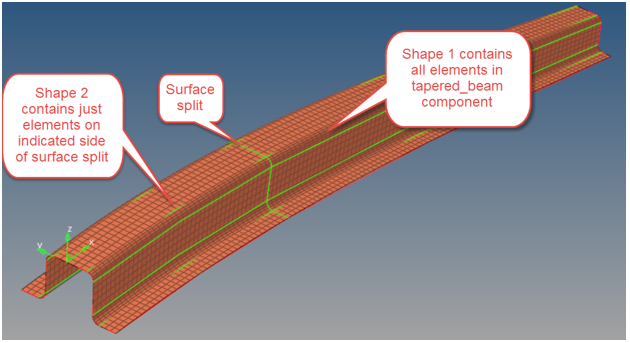
Figure 7.
-
Repeat Step 2 though 3d to create the other shape.
-
After all plies have been created, auto color by shift selecting the plies in
the Composite Browser, selecting one of the
Color icons, and click Auto
color.
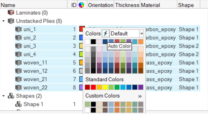
Figure 8.
Laminate Creation
Create the laminate and stack the plies.
-
Drag and drop one or more plies within the laminate so that their stacking
sequence matches the image below.
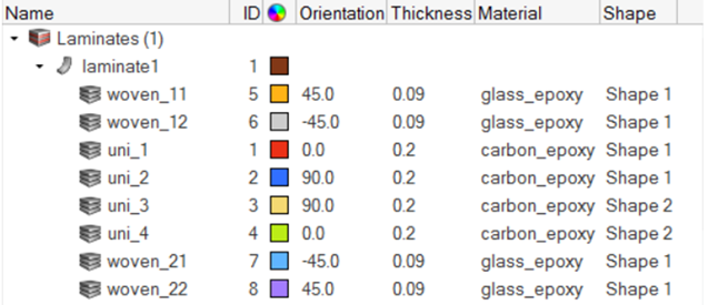 Figure 9. Note: Plies can also be automatically created from a spreadsheet import. Created plies can be exported to a spreadsheet. To access this functionality, right-click on a laminate and select Import or Export CSV.
Ply-Based Property Creation
Create the ply-based property, which specifies solver property card-specific attributes.
-
Assign PCOMPP to the elements of the tapered_ beam component. Right-click on
the property and select Assign from the context menu. Select the elements of the
tapered_beam and click
Proceed.
Figure 10.Note: No other information about the composite property layers needs to be set, regardless of solver. All layer information is defined on the play and laminate entities.
Material Reference Orientation Visualization
Plot vectors that represent the x,y,z reference orientation of each element.
-
SelectS the Material Reference option again to
deactivate it.
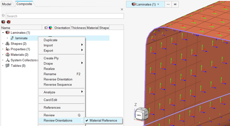
Figure 11.
Ply Direction Visualization
Plot vectors that represent the ply 1 directions on each element.
-
Select the Ply 1 Direction option again to deactivate
it.
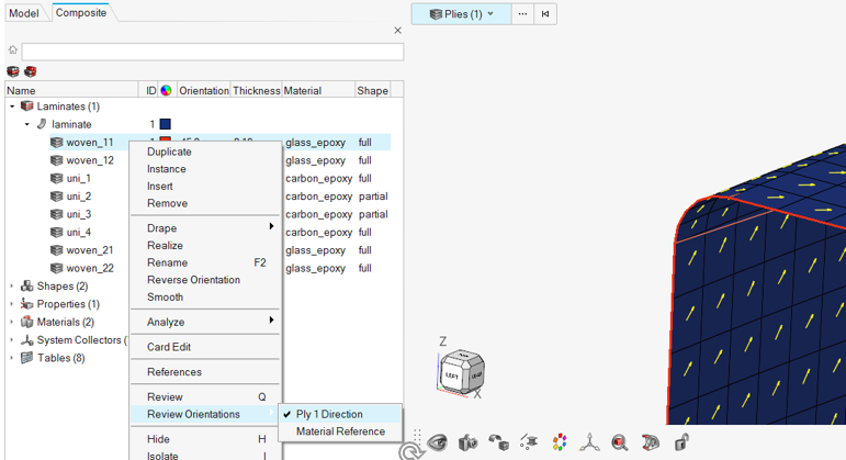
Figure 12.
Ply Shape Visualization
Plot the boundaries of each ply.
If you are using HyperWorks, select one or more plies in the Composite Browser. The boundaries of the ply will be drawn automatically. Otherwise, follow the steps below.
-
Expand the Plies folder and left-click on one or more
plies. Notice the boundaries appear highlighted in
the graphics area.
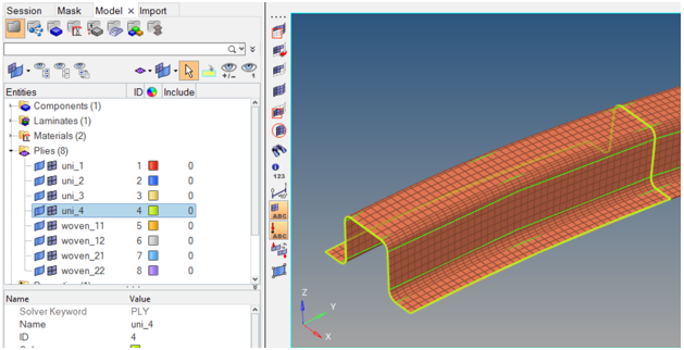
Figure 13.
Thickness and Layers Visualization
Visualize the thickness and ply layers of the laminate.
-
In HyperWorks:
-
From the menu bar, select and type 5 in the ply
visualization thickness factor input. This will temporarily increase the
displayed thickness of each ply layer for the purposes of
visualization.
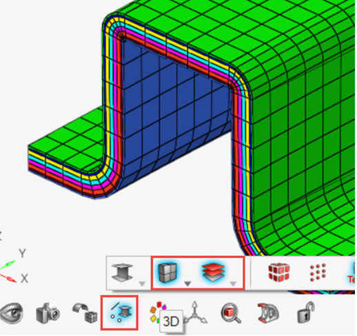 Figure 14.
-
From the menu bar, select and type 5 in the ply
visualization thickness factor input. This will temporarily increase the
displayed thickness of each ply layer for the purposes of
visualization.
-
In HyperMesh Desktop:
-
From the menu bar, select and type 5 in the ply
visualization thickness factor input. This will temporarily increase the
displayed thickness of each ply layer for the purposes of
visualization.
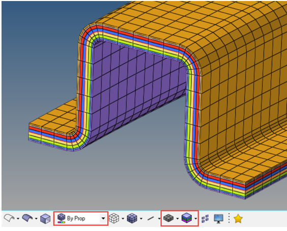
Figure 15.
-
From the menu bar, select and type 5 in the ply
visualization thickness factor input. This will temporarily increase the
displayed thickness of each ply layer for the purposes of
visualization.
Optional: Result Requests
Request typical composite results from OptiStruct.
-
Request the first ply failure/onset by checking CFAILURE. Set the following
options:
- NDIV = 2 – this will output results at the top and bottom of each ply
- OPTION = YES – this will request the output
This will print first ply onset results using the allowables defined on the MAT8 material card for each ply and the first ply failure theory specified on the PCOMPP property FT field.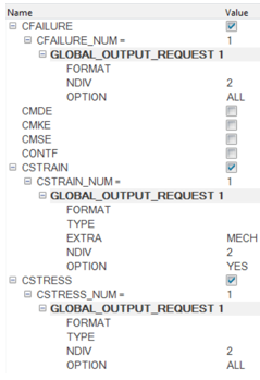
Figure 16.
Optional: Draping
Perform a draping simulation to account for local orientation changes in each ply due to placing material on a tool with compound curvature.
-
Repeat the Ply Direction Visualization exercise to visualize the draping
results. Before clicking Apply, check the Drape fiber orientation.
Note: Draping simulation generates a DRAPE table for each ply draped. The table contains thickness and orientation corrections for each element.
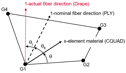
Figure 17.
Optional: Laminate Realization
Generate zone-based solver properties from the ply-based model.
This step is typically performed at the end of a model build for solvers other than OptiStruct because ply-based cards are not supported. OptiStruct directly supports ply-based composite analysis.
-
Uncheck the Include drape option and click
Realize. Notice the new properties generated and
assigned to the model.
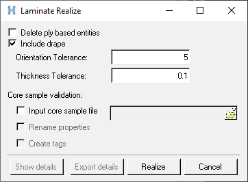
Figure 18.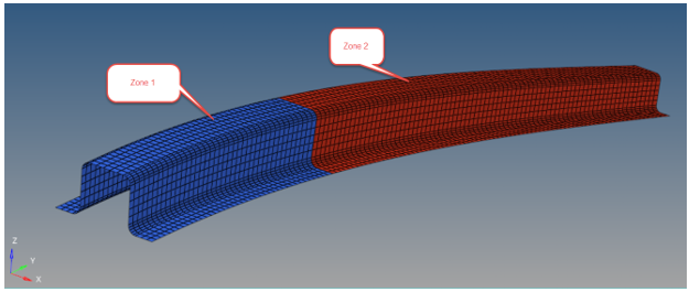
Figure 19.