HM-4010: Format Model for Analysis
The purpose of using a finite element (FE) pre-processor is to create a model that can be run by a solver. HyperMesh interfaces with many FE solvers and all of them have unique input file formats. HyperMesh has a unique template(s) for each solver it supports. A template contains solver specific formatting instructions, which HyperMesh uses to create an input file for that solver.
- Create a solver input file by using a template
- Review entities in HyperMesh to see how they will appear in the solver input file
- Define materials and properties
- Select solver element types for HyperMesh element configurations
This exercise uses the channel_brkt_assem_analysis.hm file, which can be found in the hm.zip file. Copy the file(s) from this directory to your working directory.
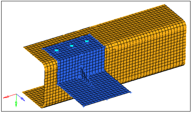
Figure 1.
Load the OptiStruct User Profile
In this step you will load the OptiStruct user profile.
- Start HyperMesh Desktop.
- In the User Profile dialog, select OptiStruct.
- Click OK.
Open the Model File
In this step you will open and view the file, channel_brkt_assem_analysis.hm.
-
Open the model file by clicking File
Open
Model from the menu bar, or
clicking
 on the Standard
toolbar.
on the Standard
toolbar.
Review the Bracket Element
In this step you will review a bracket element to identify what type of OptiStruct element it is, and to see how it will be formatted in the OptiStruct input file.
-
Open the Card Edit panel by clicking
 on the
Collectors toolbar.
on the
Collectors toolbar.
Review and Edit the Card Image
In this step you will review and edit the existing steel material’s card image by accessing the card editor from the Model Browser.
This material is defined for the channel.
-
In the Model Browser, Material
folder, click steel.
The Entity Editor opens and displays the material's corresponding data.Note: The card image indicates the material is of OptiStruct type MAT1.
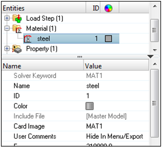
Figure 2. -
In the Entity Editor, NU (Poisson's
Ratio) field, change the value from 0.3
to 0.28.
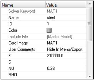
Figure 3.
Define a Material Collector
In this step you will define a material collector named aluminum for the bracket.
-
For NU (Poisson's Ratio), type 0.33.
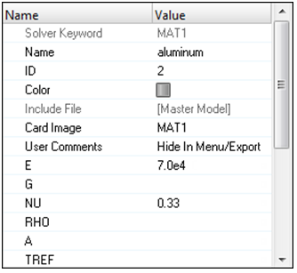
Figure 4.
Define a Property Collector
In this step you will define a property collector (PSHELL card image) that will be assigned to the channel component collector.
-
In the Model Browser, right-click and select from the context menu.
HyperMesh creates and opens a property in the Entity Editor.
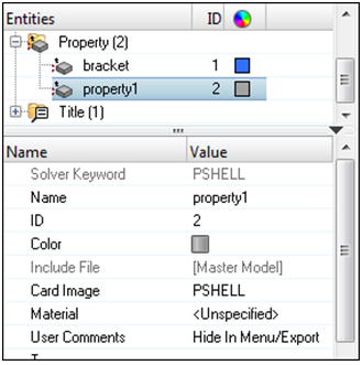
Figure 5. -
For Material, click Unspecified >> Material.
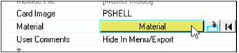
Figure 6. -
In the Select Material dialog, select
steel and then click OK. The material is assigned.
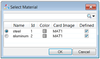
Figure 7. -
For T (thickness), type 3.0.
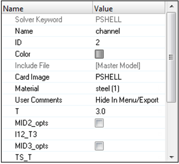
Figure 8.
Assign the Channel Property
In this step you will assign the channel property to the channel component.
-
In the Model Browser, Component
folder, click channel.
The Entity Editor open and displays the component's corresponding data.
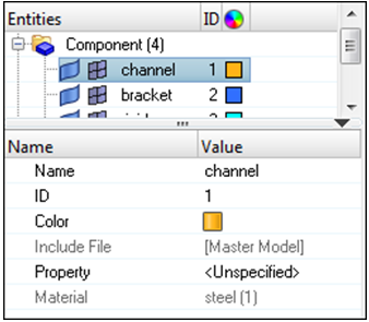
Figure 9. -
For Property, click Unspecified >> Property.
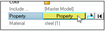
Figure 10. -
In the Select Property dialog, select
channel and then click
OK.
HyperMesh assigns the property channel to the component channel.
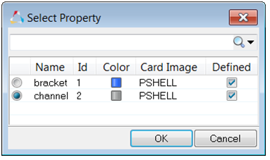
Figure 11.
Update the Bracket Property
In this step you will update the bracket property to have a PSHELL card image, a thickness of 2.0, and the aluminum material.
-
In the Model Browser, Property
folder, click bracket.
The Entity Editor opes and displays the properties' corresponding data.
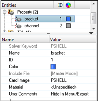
Figure 12. -
For T (thickness), type 2.0.
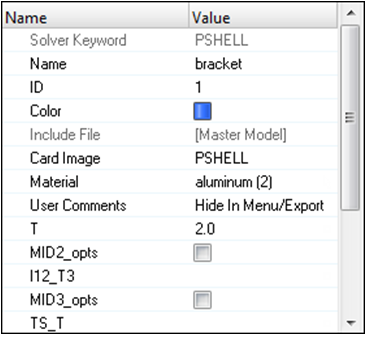
Figure 13.
Calculate Section Properties
In this step you will calculate the section properties for the bar elements (OptiStruct CBEAM) by using HyperBeam.
-
Click create.
HyperMesh opens the HyperBeam module.Note: The solid, green circle represents the cross section. Under the local coordinate system you should see the number, 10.0000, which is the circle’s radius.
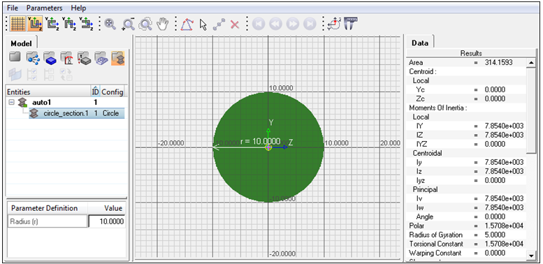
Figure 14.
Create a Property Collector
In this step you will create a property collector named bars_prop for the bar elements (OptiStruct).
-
In the Model Browser, right-click and select from the context menu.
HyperMesh creates and opens a property in the Entity Editor.
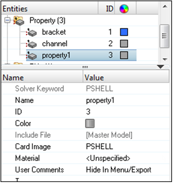
Figure 15. -
For Beam Section, click Unspecified >>
Beamsection.
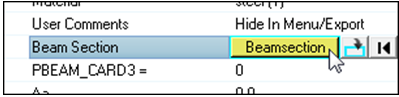
Figure 16. -
In the Select Beam Section dialog, select
6mm_Beam_Sect and then click OK.
HyperMesh assigns the beam section and populates the parameter fields in the PBEAM card with the data in the 6mm_Beam_Sect beam section.
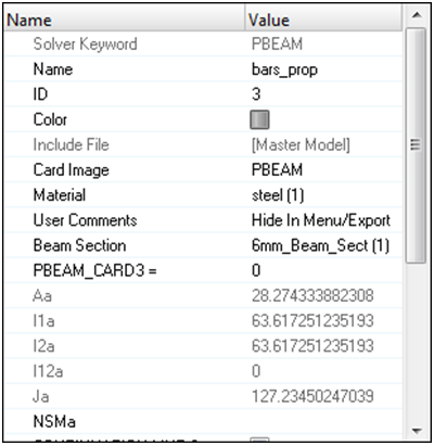
Figure 17.
Update CBEAM Elements
In this step you will update the CBEAM elements in the bolts component to use the PBEAM property.
-
In the Model Browser, Component
folder, click bolts.
The Entity Editor opens and displays the component's corresponding data.
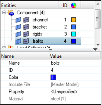
Figure 18. -
In the Select Property dialog, select
bars_prop and then click OK.
HyperMesh assigns the property bars_prop to the component bolts.
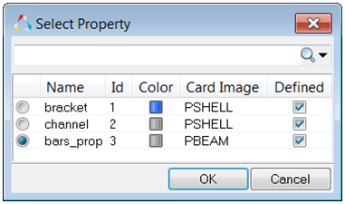
Figure 19.
Define an H3D File
In this step you will define an H3D file to be output from OptiStruct by using the control cards panel.
-
In the Card Image, select the control card FORMAT.
Note: In the card image, the FORMAT line is set to H3D. This specifies OptiStruct to output results to a Hyper3D (H3D) file, which can be viewed in the HyperView Player. A HTML report file will be output and the H3D file will be embedded in it.

Figure 20. -
In the second FORMAT line, click H3D and then select
HM.
Note: This option specifies OptiStruct to output the results to a HyperMesh binary results file, allowing the results to be post-processed within HyperMesh.

Figure 21.
Export the Model
In this step you will export the model to an OptiStruct input file.
-
In the File field, click
 .
.
Review the File
In this step you will review the contents of the channel_brkt_assem_loading.fem file.
-
Near the top of the file, note the following:
- The line FORMAT HM, which you specified in HyperMesh
- The load step (OptiStruct SUBCASE) named pressing_step, which you defined in HyperMesh
- Under the load step, the load collector IDs (OptiStruct load and constraint set identification
numbers)

Figure 22.
-
Note the load set identification number for each force (OptiStruct FORCE). It is either 1 or 2 as shown below.
These numbers correspond to the numbers under the load steps in the file.
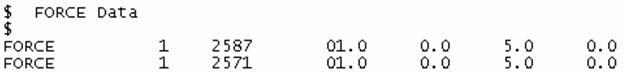
Figure 23. -
Note the constraint set identification number for each constraint (OptiStruct SPC). It is 2 as shown below, which lists a
few of the constraints. This number corresponds to the number under the load
steps in the file.
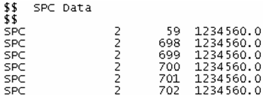
Figure 24. -
Note the load collectors, pressing_load and
constraints. Also, note their collector ID and color
ID. When the model is imported into HyperMesh, the
loads are organized into these load collectors and have these IDs and
colors.
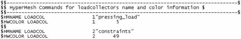
Figure 25.
Save Your Work
In this optional step you will save your work.