HM-4040: Work with Loads on Geometry
In this tutorial, you will experiment with the export of the loads applied to geometry entities. Therefore, you will need to have a template loaded. In this step, load the OptiStruct user profile and retrieve the c-channel model. By loading the OptiStruct user profile, the template will be automatically loaded.
- Create loads and boundary conditions on geometry
- Map the loads from geometry to elements
- Export to a solver deck
- Modify the mesh and remap the loads to the new mesh
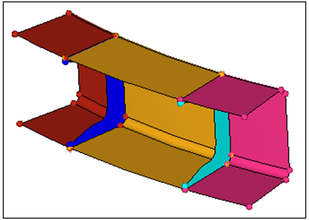
Figure 1.
Open the Model File
In this step you will open the model file, c-channel10.hm.
-
Open the model file by clicking from the menu bar, or clicking
 on
the Standard toolbar.
on
the Standard toolbar.
Create Load Collectors
In this step you will create three load collectors for constraints, forces, and pressure loads.
-
In the Model Browser, right-click and select from the context menu.
A load collector opens in the Entity Editor.
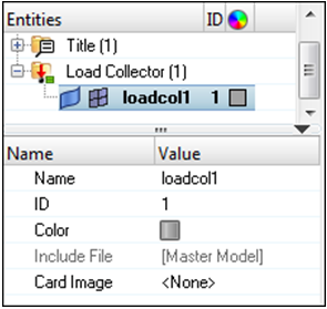
Figure 2.
Constrain Lines of the C-Channel
In the following steps you will apply constraints, pressures, and forces to geometric entities in the model. You will first constrain the bottom portion of the c-channel using line data, then you will create pressure loads on the top surfaces. Lastly, you will apply forces to the eight corners of the surfaces defining the top of the c-channel.
In this step you will fully constrain the bottom eight lines of the c-channel using the Constraints panel.
-
Select the eight lines defining the bottom portion of the c-channel as
indicated in the following image.
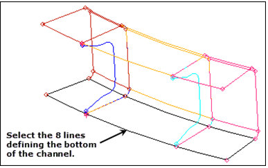
Figure 3. -
Select the dof1, dof2, dof3, dof4, dof5, and dof6 checkboxes.
Note: The selected Dofs will be constrained. Dofs 1, 2, and 3 are x, y, and z translation degrees of freedom. Dofs 4, 5, and 6 are x, y, and z rotational degrees of freedom.
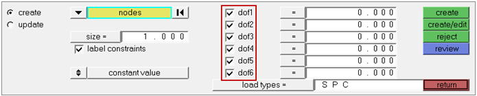
Figure 4. -
Click create.
HyperMesh applies constraints to the selected lines. Constraints are represented by triangular icons in the graphics area.
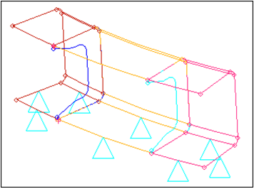
Figure 5. - Optional:
Display the degrees of freedom labels by selecting the label
constraints checkbox.
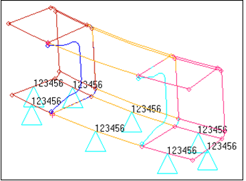
Figure 6.
Apply Pressure
In this step you will apply a pressure of 25 units normal to the top three surfaces using the Pressures panel.
-
Set the first switch to entities.
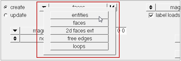
Figure 7. -
Select the three surfaces defining the top of the c-channel as indicated in the
following image.
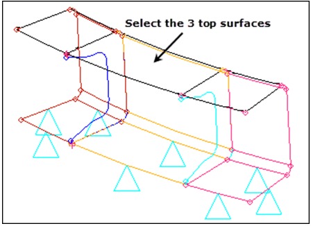
Figure 8. -
Click create.
HyperMesh applies pressure loads to the selected surfaces. Pressure loads are represented with an arrow and a label in the graphics area.Note: Labels can be template based (PLOAD here) or follow the HyperMesh terminology (P) as specified in the modeling subpanel of the Options panel.
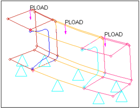
Figure 9.
Create Forces
In this step you will create forces at the eight corners of the three top surfaces.
-
Select the eight fixed points defining the corners of the c-channel’s top
surfaces as indicated in the following image.
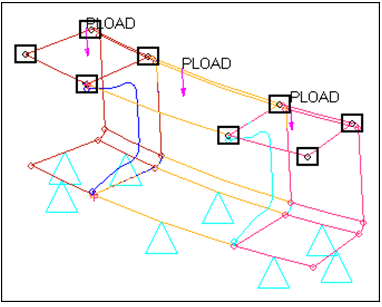
Figure 10. -
Click create.
HyperMesh creates a point force for each fixed point you selected, with the given magnitude in the z-direction.
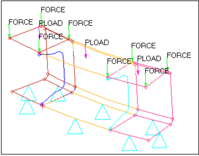
Figure 11.
Generate Elements on Surfaces
In this step, use the Automesh panel to create a quad dominant (mixed) mesh. The elements generated will be organized into their surface's component collector, which will avoid the need to set current component collectors.
-
Click mesh.
A shell mesh is created on the surfaces.
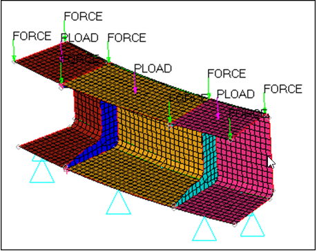
Figure 12.
Map Loads
A load collector, just like component collectors, can store both loads on geometry and loads on finite elements. These two types of loads are separate and independent, and can therefore be manipulated independently. At this time, your load collectors contain loads only in their geom side. By mapping these loads on geometry to finite elements and using your existing loadcols, you will also populate their elems side.
In this step, use the Load on Geom panel to map the loads from the geometric entities (to which the geometric loads are applied) to the mesh associated with these geometric entities for the constraints and pressure load collectors.
-
Click map loads.
HyperMesh maps the constraints previously applied to the lines to the nodes of the mesh associated to these lines.Note: These constraints are placed in the same load collector as the ones applied to the geometry, only in the elems portion.
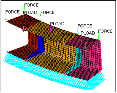
Figure 13.
Export the Model to a Solver Deck
In this step, use the Model Browser to ensure that only the already mapped loading conditions are exported.
When you export a model using an export template, only the loads on the mesh are exported. The loads on the mesh may have been applied directly to the mesh, mapped from geometry to the mesh, or both. You can use the Export tab to export loads to an ASCII solver-specific file (according to the loaded export template). The loads are exported as mesh loads.
Use the Custom template to determine which loads are exported. If all is selected, then all of the loads on the geometry that have not been mapped (if any) are mapped to the loads on the mesh, and all of the loads on the mesh are exported. If displayed is selected, then all of the displayed loads on the mesh (if any) are exported. All of the loads on the mesh associated with the displayed loads on the geometry (if any) are exported as well. If any of the loads on geometry are displayed and have not been mapped, they will automatically be mapped to the loads on the mesh and exported as well.
One load collector stores both the loads on the geometry and the loads on the mesh. The mesh (or multiple meshes) is associated with the geometric entities to which the loads on the geometry have been applied. Each load type is stored in a dedicated section of the same load collector.
Use the Display panel to separate or simultaneously visualize the loads on the mesh and the loads on the geometry. Turn off the display of the loads applied to the geometric entities to only display the loads applied to the mesh.
-
In the Model Browser, Load Collector
folder, click
 next to the loads to turn off the display of their
geometry.
next to the loads to turn off the display of their
geometry.
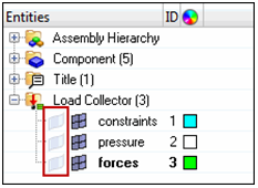
Figure 14. -
In the File field, click
 .
.
-
View advanced export options by clicking
 next to Export options.
Modify the Mesh
In this step you will modify the mesh and remap the loads to the new mesh.
-
Click return.
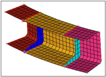
Figure 15.
Map Loads to the New Mesh
In this step you will remap the loads applied to the geometry to the new mesh.
Summary
In this tutorial, you used several boundary condition creation panels to generate constraints and various loading conditions on geometric entities.
You then experimented with the mapping of these loads on the geometry to finite elements. You also familiarized yourself with the rules that govern the export of loads on geometric entities.
No consideration to the creation of specific card images that need to accompany the various loading conditions was given. For more information on how to generate the various loading conditions for different solvers, refer to the Modeling / Solver Specific section of the HyperMesh tutorials.