AV Card
This card defines an impressed current source similar to the AI card but that makes electrical contact with a conducting surface.
On the Source/Load tab, in the Ideal sources
group, click the ![]() Impressed current
icon. From the drop-down list, click the
Impressed current
icon. From the drop-down list, click the ![]() Impressed current connected to mesh vertex
(AV) icon.
Impressed current connected to mesh vertex
(AV) icon.
The current varies linearly between the value at the start point and that at the end point. At the connection point special singular functions are used for the surface current density on the triangles to allow continuous current flow.
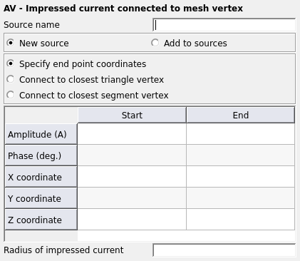
Figure 1. The AV - Impressed current connected to a triangle dialog.
Parameters:
- New source
- A new excitation is defined which replaces all previously defined excitations.
- Add to sources
- A new excitation is defined which is added to the previously defined excitations.
- Specify end point coordinates
- The coordinates of the end point r2 are specified with the X, Y, Z coordinate fields. This point must coincide with a corner point of one or more triangles.
- Connect to closest triangle vertex
- The coordinates of the end point r2 are not known. In this case the X, Y, Z coordinate fields of the end point are not used. Feko searches through all the metallic triangles for the corner point that is closest to the start point r1 of the current element. This is then the end point r2.
- Connect to closest segment vertex
- The coordinates of the end point r2 are not known. In this case the X, Y, Z coordinate fields of the end point are not used. Feko searches through all the metallic segments for the vertex that is closest to the start point r1 of the current element. This is then the end point r2.
- Amplitude (A)
- Current amplitude (in A) at the start, r1, and end, r2, points.
- Phase (deg.)
- Phase of the current at the start point in degrees.
- X, Y, Z coordinate
- Coordinates of the start and end points in m. (Note that all the coordinate values are optionally scaled by the SF card.)
- Radius of impressed current
- This parameter is optional. If specified, and different from zero, this value gives a finite wire radius for the impressed current element. Feko then assumes that the current is uniformly distributed on the wire surface and uses the exact wire integral. If the parameter is not specified, the current filament approximation is used. This value is optionally scaled by the SF card.
- All the restrictions given in the discussion of the AI card also apply in this case.
- The start point of the impressed current segment may be connected with AI cards or further AV cards. If there is a current discontinuity at this point, the resulting point charge is not considered (see the discussion given with the AI card). Line charges along the current path and surface charges on the triangles are correctly taken into account. At the connection point r2 a continuous current model is used so that a point charge is not possible here.

Figure 2. Impressed line current with a linear current distribution and electrical contact to conducting triangles.