AR Card
This card uses the radiation pattern of an antenna as an impressed source. The data is read from file or defined in the .pre file.
On the Source/Load tab, in the Equivalent
sources group, click the ![]() Radiation pattern (AR) icon.
Radiation pattern (AR) icon.
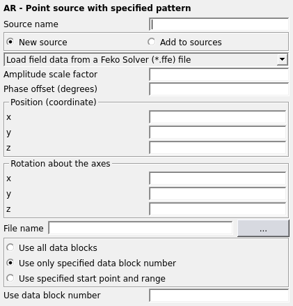
Figure 1. The AR - Point source with specified pattern dialog.
Parameters:
- New source
- A new excitation is defined which replaces all previously defined excitations.
- Add to sources
- A new excitation is defined which is added to the previously defined excitations.
- Load field data from
-
- Feko Solver (*.ffe) file
- Read the radiation pattern from an .ffe format file, created with DA and FF cards.
- CST far field scan (*.ffs)
- Read the radiation pattern from a CST far field scan.
- external data file
- Read the radiation pattern from an ASCII file (the format of this file is described below).
- The file data follows in the (*.pre) input file
- The radiation pattern is specified in the .pre file following the AR card (the format is described below). With this option FOR loops can be used to generate patterns from known functions.
- Use last pattern defined at previous AR card
- When using multiple AR cards (different radiating antennas in the same model) then it is quite common that the shape of the pattern is identical. If this is the case it is allowed to load the pattern just once and at subsequent AR cards to check this option. Then the last defined pattern will be used and memory can be saved (no need to store it again). Note that it is still possible to set the antenna position, orientation as well as amplitude and phase individually.
- Amplitude scale factor
- The field strength values in each direction is determined from the data. This parameter is used to scale the amplitude of the entire pattern by a constant value.
- Phase offset (degrees)
- This parameter specifies a constant additional phase for the entire pattern.
- Position (coordinate)
- In this group the X, Y and Z coordinates of the source point (the position where the antenna is located) are entered in meters. This value is affected by the scale factor of the SF card if used.
- Rotation about the axes
- In this group the angles with which the imported pattern is rotated around the x, y and z axes are entered in degrees. These fields are referred to as , and in the rest of this discussion.
- File name
- The name of the .ffe, .ffs or ASCII input file.
- Use all data blocks
- Import all data blocks from the specified .ffe or .ffs file. The data is interpolated for use at the operating frequency.
- Use only specified data block number
- Use the data from the nth frequency block in the specified .ffe or .ffs file.
- Use specified start point and range
- Select a specific far field pattern in a .ffe or external file.
- Start from point number
- This parameter is only relevant when the data is read from a .ffe or an external file, and gives the line number of the first line to read from the input file. If the data must be read from the beginning of the file, the value in this field should be set equal to 1. This parameter is used when the .ffe file contains more than one pattern. For example, if the file contains the pattern at various frequencies, the correct pattern can be selected by setting this field to the appropriate value for each frequency. If the .ffe file is of a newer format and contains header data in addition to the data blocks, the point number refers to the actual point number excluding blank lines, comment lines and header lines.
- Number of points
- The number of angles in the pattern.
- Number of points
- The number of angles in the pattern.
The radiation pattern of the antenna must be specified in spherical coordinates ( , ) with the phase centre located at the origin of the local coordinates (as used in the pattern data). If this is not the case, the phase of the far fields will not be correct. (For example, if an .ffe file is exported with Feko to be used with the AR card, the origin should be shifted with the OF card to the phase centre of the antenna.) The vertical and horizontal components of the complex electric field and/or must be specified at discrete angles ( , ) with i and j larger or equal to 1 and smaller or equal to the number of points specified for the respective angles. The field values are entered in Volts and the actual far fields are calculated from
The permissible range of the angles is 0°...180° and they must be in ascending order, that is . However, the angles do not have to be equidistantly spaced. (Therefore in the case of a highly directive antenna a denser grid can be used close to the main beam direction.) The same applies to the angles where the permissible range is 0°...360°. For field angles outside the start and end values defined in the data (for , , or ), the field strengths and are set to zero, so that a sector radiator can be realised. The values at field angles within the defined range are determined by bilinear interpolation. To realise a complete radiation pattern, rather than a sector radiator, the angles should be defined so that , , and .
The radiation pattern, specified in the local spherical coordinate system ( , ) of the antenna, is read and initially placed at the origin of the global coordinate system in which the .pre file is constructed. The pattern is now rotated by an angle around the Z axis, by around the Y axis and by around the X axis. (The rotation is identical to the rotation executed by the TG card and the rotation matrix M is applicable to both the TG and AR cards.) Finally the pattern is shifted to the specified location.
If the AR card is used simultaneously with a ground plane (BO card), Feko includes the influence of the ground plane on the radiation pattern. The imported pattern must therefore be the free space radiation pattern of the antenna (in the absence of the ground plane). If this is not the case the influence of the ground plane is considered twice.
The use of the PW card to specify the radiated power is allowed. The field amplitudes and will be scaled accordingly. Multiple radiation patterns can be used simultaneously, and also with other sources such as an incident plane wave. In such a case, the coupling is not considered when the radiated power is determined.
The AR card cannot be used with special Green’s functions for a layered sphere or for a layered substrate.
- an .ffe file With this option, the radiation pattern is read from an .ffe file created with Feko (using the DA and FF cards). All the data of the radiation pattern (angles and field values) are determined from the file. The user should ensure that the frequency is correct. If an antenna is analysed with Feko, the far field can be exported to the .ffe file using the commands (for 5° angle increments)
DA: 0 : 0 : 1 : 0 : 0 :  :  :  : 0
FF: 1 : 37 : 73 : 0 : 0 : 0 : 0 : 5 : 5 :  :  : 0
Note 37 points are used for and 73 points for to ensure that the radiation pattern is closed (see also the comment above).
This can then be imported as a source into another model with the commandAR: 0 : 1 : 1 : 37 : 73 : 1.0 : 0.0 : 0.0 : 0.0 : 0.0 : 0.0 : 0.0 : 0.0 : "file.ffe" - an external ASCII fileWith this option, the data is read from the specified external data file. Each line contains 6 space delimited data fields in the following order:
- The angle in degrees
- The angle in degrees
- Amplitude of the field strength in V
- Phase of the field in degrees
- Amplitude of the field strength in V
- Phase of the field in degrees
The inner loop should be with respect to the angle so that the order of the lines is as follows (where N is the number of points and M is the number of points):
(3) - after this line in the .pre file
This case is similar to reading an external ASCII file, except that the data is read directly from the .pre input file. The six data fields mentioned for the case of an ASCII file must appear in the 6 columns of 10 characters, starting at character 31 and ending at character 90 in the lines following the AR card. When this option is selected the card dialog shows additional input fields where the user can specify these values for each point. The data lines may be separated by comment lines (EDITFEKO, however, does not support this) and FOR–NEXT loops may be used. Even when using FOR loops the card dialog in EDITFEKO can be used to generate a typical line.
An ideal sector radiator:
** Application example for the AR card: Sector radiator
** No other structures considered
EG: 0 : 0 : 0 : : : : : : : : : : 1
** Set the frequency
FR: 1 : 0 : : : : 100e6
** Specified radiated power
PW: 1 : : : : : 10
** Define the sector radiator
AR: 0 : 3 :  : 2 : 2 : 1.0 : 0.0 : 0.0 : 0.0 : 0.0 : 0.0 : 0.0 : -70
  :  :  :  :  :  : 75 : 0 : 0 : 0 : 1 : 0
  :  :  :  :  :  : 105 : 0 : 0 : 0 : 1 : 0
  :  :  :  :  :  : 75 : 140 : 0 : 0 : 1 : 0
  :  :  :  :  :  : 105 : 140 : 0 : 0 : 1 : 0
** Check: Compute the full 3D radiation pattern with 5 deg stepping
FF: 1 : 37 : 73 : 0 : 0 : 0.0 : 5.0 : 5.0 : : : : 0
** End
EN
Feko determines a directivity of 10.1 dBi. The radiation pattern is easily validated by calculating the far field as shown with the FF card in the last step. The 3D far field is depicted in the figure below.
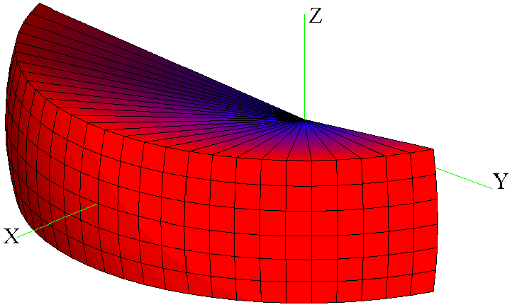
Figure 2. 3D radiation pattern of the sector radiator.