Create Spots
Create an entity to apply loads, constraints, or other boundary conditions to.
- On the Project Tree, select the Assembly workbench.
-
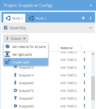
Click on .
Figure 1. 
-
In the Create spot dialog, create one of the
following:
Spot Type Steps Create Rectangular Spot - Select the Rectangle tab.
- Specify the spot dimensions.
- Specify the Coordinates of the spot center projection.
- Specify the Rotation angle.
Create Circular Spot - Select the Circle tab.
- Specify the spot dimensions.
- Specify the Coordinates of the spot center projection.
- Specify the Rotation angle.
Create Spot on Cylinder - Select the Spot on cylinder tab.
- Select any cylindrical face in the modeling window.
Create a Spot in the modeling window - In the dialog, select the tab for the desired spot shape.
- In the modeling window, select a face on any part.
- Click and drag with the left mouse button to reposition the spot
on the face.Note: You can drag a spot to the generated "red snap point" on a face to position it as well. Drag the spot close to the point and release when the crosshair cursor appears.
- Rotate a spot around the center.
- Hover over the vertices (4 corners for a rectangle, 2 sector corners for a circular cutout).
- When the hand cursor appears, hold down the left mouse button, rotate to the desired position, and release.
- Resize a spot.
- Hover over the edge of the spot.
- When the edge is highlighted in red, hold down the left mouse button, drag to the desired size, and release.
- Click OK.