Non-Linear Separating Contact and Bolt Pretensioning - Hanger Beam
Perform nonlinear spearating contact analysis and setup bolt/nut tightening
loads.
Purpose
SimSolid performs meshless structural
analysis that works on full featured parts and assemblies, is tolerant of
geometric imperfections, and runs in seconds to minutes. In this tutorial,
you will do the following:
Perform assembly analysis
Perform nonlinear separating contact analysis
Use SimSolid bolt tensioning functions
Compare SimSolid results with those obtained in
traditional FEA.
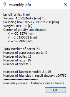
Model Description
The hanger beam model in this tutorial has 70 parts, 16 bolts/nuts, and 32
washers.
Figure 1.
The following files are needed in this tutorial:
Hanger beam.x_t (CAD source file)
Hanger Beam.ssp (SimSolid project
files with the first load case solved. This is where you will start the
tutorial.)
Hanger Beam SOLVED.ssp (SimSolid
project file with all load cases solved. Provided as a reference.)
Important: The introductory steps of this tutorial provide
information on how the first analysis was created. If you wish to skip this, go
straight to Open Project.
Import Geometry
Import model geometry into SimSolid.
Open a new SimSolid session.
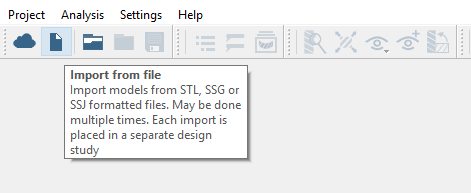
Click the (Import from file) icon.
Figure 2.
In the Open geometry files dialog, choose
Hanger Beam.x_t.
Click Open.
The assembly will load in the modeling window.
The Automatic
connections dialog will open.
Create Connections
Specify gap and penetration tolerances to create automatic connections.
In the Project Tree, click
on the Connections branch.
In the Connections workbench toolbar, click (Automatic connections).
Specify Gap and Penetration tolerances as 2.
Set Connection resolution level to Increased.
Click OK.
Note:
SimSolid will create connections even in areas with overlapping
geometry.
SimSolid will automatically identify bolts, nuts and washers.
Sliding contact will be applied automatically in bolt shanks,
bonded otherwise.
Create Structural Linear Analysis
Create a structural linear analysis with immovable constraints and a handlebar
load.
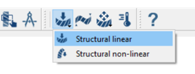
On the main window toolbar, click (Structural analysis).
Choose Structural linear.
Figure 3.
The new analysis will appear in the Project Tree
under Design study 1 and the Analysis Workbench will
open.
Create Immovable Supports
Create immovable supports
In the Analysis Workbench, click (Immovable support).
In the dialog, verify the Faces radio button is
selected.
In the modeling window, select the faces on the end of
the Lowerbeams (Face 2, Lowerbeam, Face 26, Lowerbeam, Face 29, Lowerbeam, Face
1, Lowerbeam).
Click OK.
The new constraint, Immovable 1, will appear in the Project Tree. A visual representation of the straint will
appear on the model.
Create Force
Create the hanger beam load.
In the Analysis Workbench, click (Force/Displacement).
In the dialog, ensure the Faces radio button is
selected.
In the modeling window select Face 18, Hangerbeam and
Face 2, Hangerbeam.
Specify a Z direction force of -1000 N.
Click OK.
The new force, Load/Displ. 1, will appear in the Project Tree. Vectors representing the load will appear on
the model.
Change Max Number of Adaptive Solutions
Define the number of solution passes.
In the Project Tree, double-click on
Solution settings.
In the dialog, set the objective to Custom and increase
the number of adaptive solutions to 4.
Activate the Adapt to features checkbox.
Click OK.
Assign Materials
Apply materials to all parts in the assembly.
In the Project Tree, click on
the Assembly branch.
In the Assembly workbench, click (Apply materials).
Pick Steel from the Generic materials list.
Click Apply to all parts.
Click Close.
In the Assembly branch of the Project Tree,
material properties are identified for each part.
Run Analysis
Solve the analysis.
In the Project Tree, open
the Analysis Workbench.
Click (Solve).
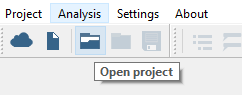
Open Project
Open the SimSolid project file.
Start a new SimSolid session.
Click the (Open Project) icon.
Figure 4.
In the Open project file dialog, choose Hanger Beam.ssp
Click OK.
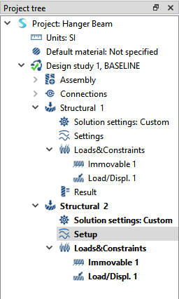
Create Non-linear Separating Contact Analysis
Copy Structural 1 and edit to create non-linear separating contact
analysis.
In the Project Tree, right-click Structural
1 and choose Copy.
The copy will appear as Structural 2 in the Project Tree.
Under Structural 2, right-click on Setup and choose
Edit.
Figure 5.
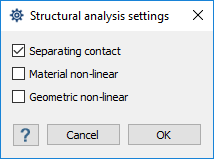
In the dialog, activate the Separating contact
checkbox.
Figure 6.
Click OK.
Edit Contact Conditions
Change contact conditions for selected connections.
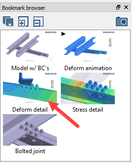
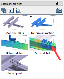
In the Bookmark browser, click Bookmark 5.
Figure 7.
The modeling window will update with the saved
view.
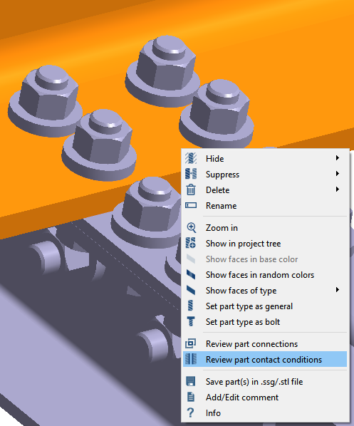
In the modeling window, right-click on the
Hanger beam (shown in orange) and select
Review part contact conditions.
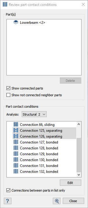
Figure 8.
In the dialog, hold down Control and click to select
Connection 125 and Connection
126.
Click the Edit contact conditions button.
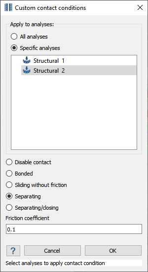
Figure 9.
In the Contact conditions dialog, select
Structural 2.
Activate the Separating radio button.
Figure 10.
For the Friction coefficient, specify 0.1.
Click Close.
Run Analysis
Solve the analysis.
In the Project Tree, open
the Analysis Workbench.
Click (Solve).
Compare Results
Observe the difference in results between structural linear analysis and non-linear
separating contact.`
In the Project Tree, select the Structural
1 branch.
In the Bookmark browser, choose Bookmark 3.
This bookmark shows the deformation detail. Figure 11.
In the Project Tree, select the Structural
3 branch.
The modeling window will update to show
deformation detail for Structural 2.
Optional: Switch back and forth between Analysis branches to highlight the differences in
the results.
Repeat steps 1
through 4 for
Bookmark 4 (stress detail).
Figure 12.
View Separation and Contact Forces
View the separation and contact forces at the separating surface.
These forces are represented as colored values at each connection point (not a true
contour). You used increased resolution when creating connections to get a denser array
of points to plot.
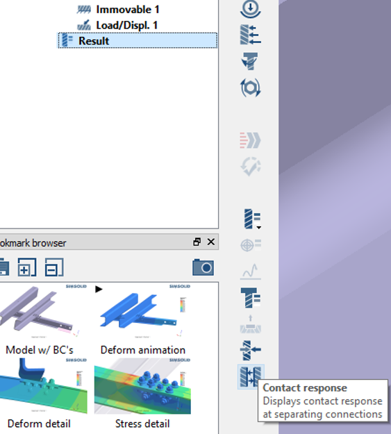
In the Project Tree, select the
Results branch under Structural 2.
On the Analysis Workbench, select (Contact Response).
Figure 13.
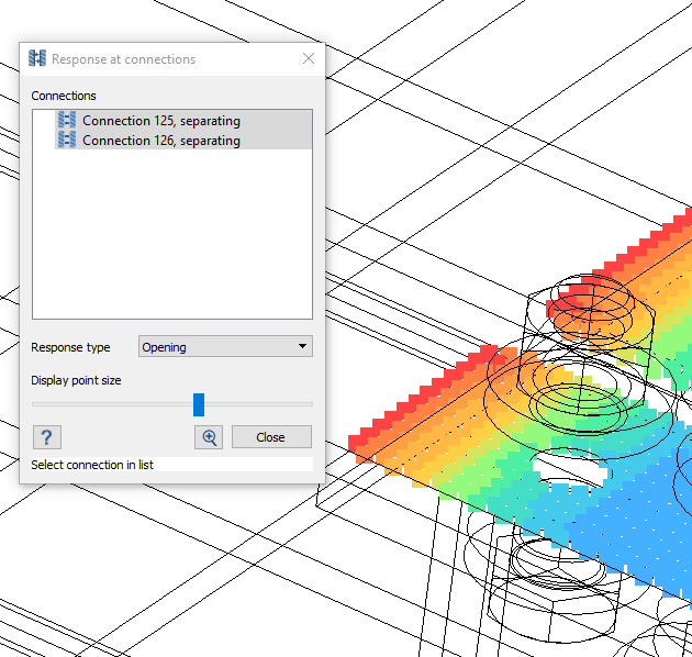
In the Response at connections dialog, hold down
Control and click to
select Connection 125 and Connection
126.
Select the response type you wish to view.
Use the slider to increase or decrease the size of the colored points.
Figure 14.
Click Close.
Setup Bolt/Nut Tightening
Copy analysis and edit to include bolt/nut tightening.
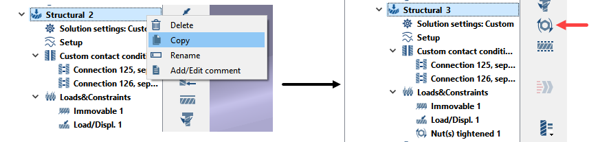
In the Project Tree, right-click on
Structural 2 and select
Copy.
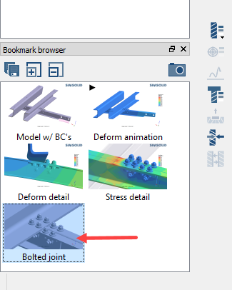
The copy will appear as Structural 3 in the Project Tree. Figure 15.
In the Bookmark browser, select Bookmark 5 (Bolted
joint).
Verify Structural 3 is selected in the Project Tree.
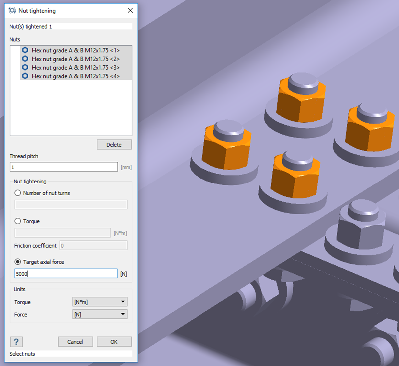
In the Analysis Workbench toolbar, click (Nut tightening).
In the modeling window, select the 4 nuts attached to
the hanger beam as shown in orange in Figure 16.
Figure 16.
For Thread pitch, enter 1 mm.
Activate the Target axial load radio button and enter
5000 N in the text box.
Click OK.
Run Analysis
Solve the analysis.
In the Project Tree, open
the Analysis Workbench.
Click (Solve).
Compare Results
Observe the difference in results between structural linear analysis and non-linear
separating contact.`
In the Project Tree, select the Structural
1 branch.
In the Bookmark browser, choose Bookmark 3.
This bookmark shows the deformation detail. Figure 17.
In the Project Tree, select the Structural
3 branch.
The modeling window will update to show
deformation detail for Structural 2.
Optional: Switch back and forth between Analysis branches to highlight the differences in
the results.
Repeat steps 1
through 4 for
Bookmark 4 (stress detail).
Figure 18.
Compare with Traditional FEA
Run the same analysis using your existing traditional FEA application.
Use the model files to run this same analysis with your traditional FEA
application.
Important:
Do not merge or simplify geometry, use bonded and sliding contact
same as SimSolid.
Check for part overlaps
Make sure elemetn density is acceptable for smaller parts
 (Import from file) icon.
 (Automatic connections).
 (Structural analysis).
 (Immovable support).
 (Force/Displacement).
 (Apply materials).
 (Solve).
 (Open Project) icon.
 (Contact Response).
 (Nut tightening).