Distributed Mass
Apply distributed mass in SimSolid.
Purpose
SimSolid performs meshless structural
analysis that works on full featured parts and assemblies, is tolerant of
geometric imperfections, and runs in seconds to minutes. In this tutorial,
you will do the following:
- Learn how to apply distrubuted mass bu total area or mass per area.
Model Description
The following model file is needed for this tutorial:
- DistributedMass.ssp

Figure 1.
This file has the following specifications:
- Material is set to Steel for all parts.
- Regular connections with 3mm gap and penetration tolerance.
- Modal analysis is pre-defined.
Open Project
Open the SimSolid project file.
-
Click the
 (Open Project) icon.
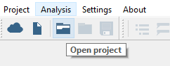
Figure 2.
Option 1: Apply Distributed Mass by Total Mass
Use total mass to apply distributed mass to the model.
This is one of two methods for applying distributed mass. To instead apply using mass per area, see Option 2: Apply Distributed Mass by Mass Per Area.
-
On the main window toolbar, select
 (Clip assembly with plane).
This will allow you to see the inner faces of the vessel.
(Clip assembly with plane).
This will allow you to see the inner faces of the vessel. -
On the Analysis Workbench, click
 (Distributed Mass).
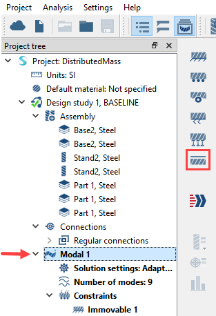
Figure 3. -
Select the inner faces of the vessel as shown in orange in Figure 4.
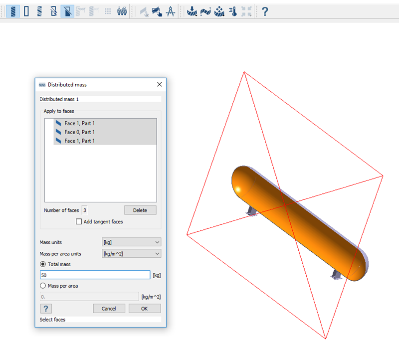 Figure 4.
Option 2: Apply Distributed Mass by Mass Per Area
Use total mass to apply distributed mass to the model.
This is one of two methods for applying distributed mass. To instead apply using total mass, see Option 1: Apply Distributed Mass by Total Mass.
-
On the main window toolbar, select
(Clip assembly with plane).
This will allow you to see the inner faces of the vessel.
-
On the Analysis Workbench, click (Distributed Mass).
Figure 5. -
Select the inner faces of the vessel as shown in orange in Figure 4.
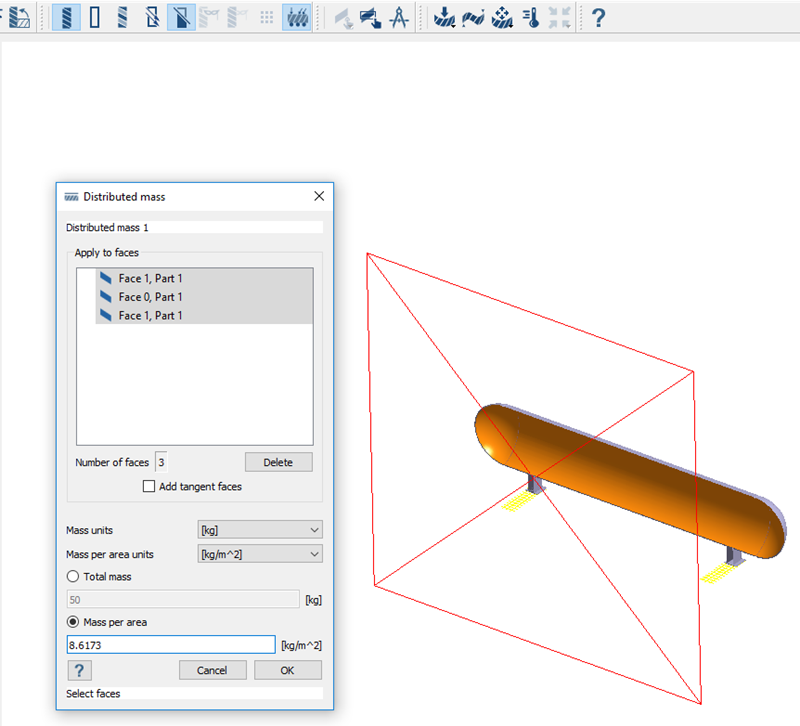 Figure 6.
Run Analysis
Solve the analysis.
- In the Project Tree, open the Analysis Workbench.
-
Click
 (Solve).
Review Results
Plot the displacement contour.
-
On the Analysis workbench toolbar, click the
 (Results plot) icon.
-
Select Displacement Magnitude.
The Legend window will open and display the contour plot. The Frequency (Hz) window will open and display the modes.
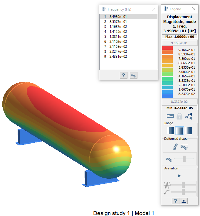 Figure 7.
Compare Results With and Without Distributed Mass
Run the analysis without distributed mass and compare the results.
-
Create a second modal analysis.
-
Choose Copy from the context menu.
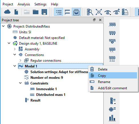 Figure 8. Modal 2 will appear in the Project Tree.
-
Choose Copy from the context menu.
-
Remove distributed mass from Modal 2.
- In the Project Tree, expand the Modal 2 branch.
- Under Constraints, right-click on Distributed mass 1 and choose Delete from the context menu.

Figure 9. -
Solve Modal 2.
- In the Project Tree, ensure Modal 2 is selected.
-
On the Analysis Workbench, click
 (Solve).
The Results branch will appear under the Modal 2 branch in the Project Tree. -
Plot Displacement Magnitude for Modal 2.
-
On the Analysis workbench toolbar, click the
(Results plot) icon.
- Select Displacement Magnitude.
-
On the Analysis workbench toolbar, click the
-
In the Project Tree, click between the
Results branches for Modal 1 and Modal 2 to compare
the Displacement Magnitude plots.
Figure 10. Results with Distributed Mass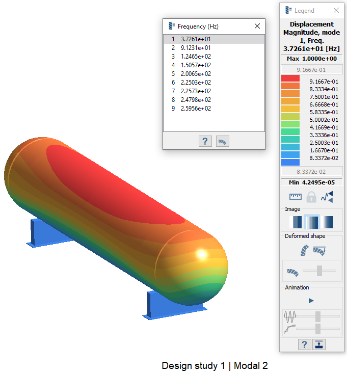
Figure 11. Results without Distributed Mass