The jetting effect is modeled as an overpressure applied to each element of the airbag
(Figure 1).(1)
with:
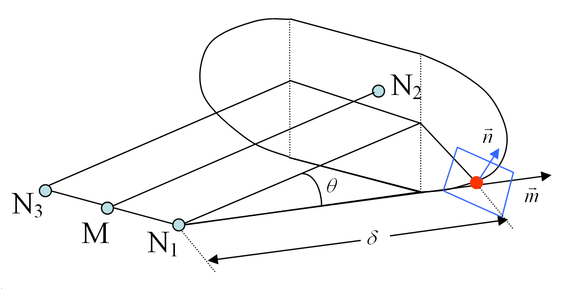
Being the normalized vector between the projection of the center of the element upon
segment (, ) and the center of element as shown in Figure 1.
The angle between the vector and the vector .
The distance between the center of the element and its projection of a point upon
segment (, ).
The projection upon the segment (, ) is defined as the projection of the point in direction upon the line (, ) if it lies inside the segment (, ). If this is not the case, the projection of the point upon
segment (, ) is defined as the closest node or . If coincides to , the dihedral shape of the jet is reduced to a conical
shape. Figure 1. Jetting Effect Schema