Graphic Entity Attributes Panel - Entity List Tree
For MBD models, the entity list tree organizes the graphical entities contained in a model by category.
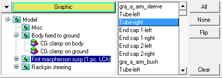
Figure 1. Entity list tree
| All | Click All to select all entities in the entity list. |
| None | Click None to deselect all highlighted entities in the list. |
| Flip | Click Flip to exchange the currently selected entities for the unselected entities in the list. |
| Clear | Click Clear to clear the entities in the list. |
Graphical entities are meant to provide a visual representation of the model. You can have primitive graphics in your model, or you can create user defined graphics where the user defined graphics are a collection of primitive graphics.
The Graphics Entity Attributes panel allows you to control the visualization parameters of these graphics. You can use the panel to turn the graphical display on or off, to visualize the ID of the entity or to use the entity in a “fit” of the model window. In addition, the meshing options as well as the color of the graphical entities can be controlled from this panel.
In order to change the attributes of an entity, it must first be selected either from the list tree or picked from the graphics area. Attributes apply only to selected entities.
Entities can be selected from the list tree in groups or individually. When an entity type is selected from the entity option menu, only that entity type can be picked from the MotionView window. For example, if only components are displayed in the list tree, only the components displayed in the MotionView window can be picked; none of the other entities can be picked.
When you select an entity from the screen, it is highlighted in the entity list tree. The entity list tree also reflects how each entity is displayed on the screen. For example, if you pick Comp 1(1) from the entity list tree and choose the mesh line display, the button next to Comp 1(1) is displayed in mesh line mode. The component ID, (1) for example, is always displayed in the entity list.
When you select ID to be displayed, the ID is displayed on the screen next to the mouse cursor for a selected part or component. Select Sort by ID to list the components in ascending order, by ID.
After you create a group, it is displayed on the Entity Attributes panel. Similarly, when you load a model and it contains 1-D, 2-D, or 3-D components, the components are sorted into their respective group. Click the Entity filter and select Groups to view the groups and their components.