Use the Replicate tool to replicate a mesh from one location to another, with options
to keep the original mesh, as well as to replicate into multiple copies. The replicated
elements replace the original elements, maintaining relevant information like properties,
thicknesses, and other solver attributes.
This is useful when there are multiple instances of the same feature in a model. You
may clean and prepare the mesh for just one of the instances, and then replicate
those changes to the other locations. This is also useful for making design changes,
such as moving a feature from one location to another or creating multiple instances
of a feature.
From the Elements ribbon, click the
Replicate tool.
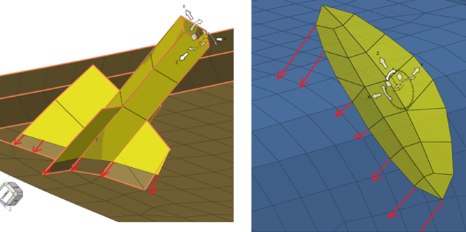
Figure 1.
Optional: On the guide bar, click to change mapping and
rebuilding options.
Select elements to replicate.
Click the Stitch Edges selector then select 1D elements
or mesh edges across which the elements will be extended or trimmed.
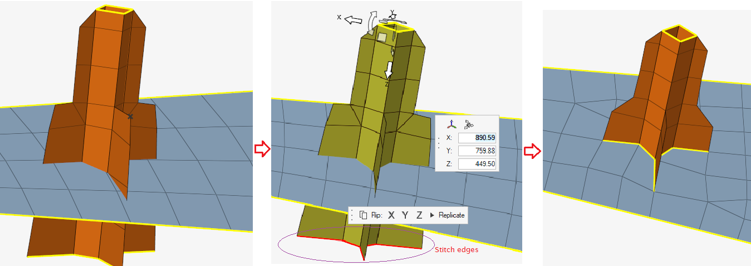
Click Move on the guide bar.
Optional: In the microdialog, toggle the Keep
original button.
When on, the original elements are kept. Use the text box to select the
number of instances of the feature to replicate. This is supported both for
mesh associated to geometry as well as mesh not associated to
geometry.
When off, the original elements are removed, and the area is filled in
with a patch. This is supported only for mesh not associated to
geometry.
Position the replicate instance(s) using the Move tool
manipulators.
Tip: Quickly reflect about the X, Y, or Z axis using the icons
in the microdialog.
Click Replicate on the guide bar
or the microdialog.
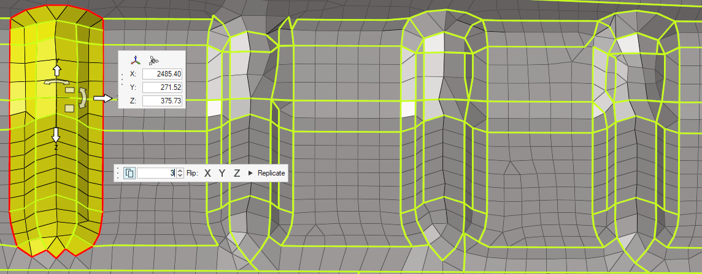
Mapping Methods
Choose a mapping method by clicking on the
Replicate tool guide bar.
Auto
Smarty decide what to do based on the selected feature. This method
utilizes imprint, morph, and rebuild functionalities internally.
Figure 2.
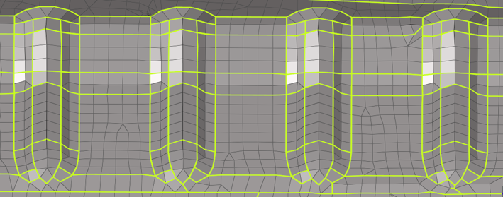
Extend
This function comes in handy when extending or trimming the feature to
the base mesh. Refer to the example images below from left to right for
an illustration of the usage.
Note: In this case, the copy option is
turned off in order to trim the base mesh with the feature and
create conformal feature edges on the base (as shown in the right
most image).
Figure 3.
Morph
This option is best suited when there is a slight mismatch in the size
and shape of the source and base feature; both features are morphed in
order to create conformality.
None
If you would like to maintain the source topology unchanged, it is
recommended to use this mapping method. In the following example, the
left bead has been used as a source topology.
Figure 4. Before replicating with the mapping method set to None.
Figure 5. After replicating with the mapping method set to None.
Observe that the source bead topology is being replicated on the rest of
the beads, and they look exactly the same as the source topology; only
surrounded nodes are moved/morphed and stitched to the source.

 to change mapping and
rebuilding options.
to change mapping and
rebuilding options.