Define Tracers for Streamlines
- Optional:
Specify the injection break.
This value specifies the time difference between two injections of tracer sets. For example with an ink injector, the injection break determines the time interval in which no ink is injected.
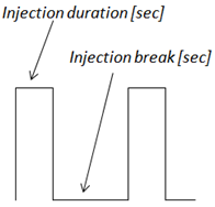
Figure 1. Injection Duration/Break for an Endless Pulse ModeRestriction: This parameter is only available to be edited if the Pulse option is set to Endless (see above). - Optional:
Defining tracers also generates entries in the Results Browser (located under the CFD Rakes folder). You can use
the tracers entry to manage the display of the tracers for a particular
rake.
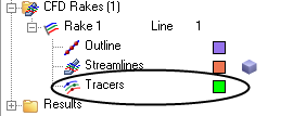
Figure 2.- Activate/deactivate the tracers by clicking on the icon next to Tracers.
- Change the color of the tracers by right-clicking on the color box (and then selecting a new color from the palette). The color selection will only take effect if the Color by option is set to Rake (on the Tracer tab).