Measures can be defined on the nodes of a cross-section enabling a deeper analysis of
the deformation of the section.
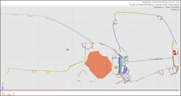
Typical applications of measuring values on the cross-section
include plotting the position or distance between nodes on the cross-section (as measuring the
intrusion shown in the image below). A distance between measure on the opposing sides of the
vehicle B-pillar section shows how close the structure is intruding into the occupant
compartment. The measurement on a cross-section can be helpful in identifying the minimum
distance separating the two sides that may not be possible by considering only the mesh
nodes. Figure 1.
In addition to making position based measurements on the nodes of a cross section,
you can also graph the section or any portion of the continuous segments by defining a node
path on the cross-section cuts and cross plotting node X, Y, or Z locations (or the distance
between them).
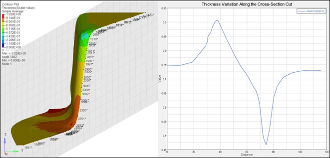
Result variations along a section cut can also be studied by defining a
node path along the cut. This helps engineers to assess the variation of a result along a
user specified path on a cut section. For stamping, it is often necessary to validate
simulation against test data. One of the common ways to obtain test data is to cut the
stamped part into two pieces and then measure the thickness along the length of the cut. To
be able to compare FEA results against such data, a path needs to be defined along the cut
section of the FEA model and must be able to plot a selected FEA results type as illustrated
below: Figure 2.
The nodes on the section cuts are also accessible from the Notes panel to attach any text based annotations to the cross
sections.
Cross-section Node Restrictions
Cross-section nodes are available in the Measure and Notes panel only, and are not available anywhere else in
HyperView (for example, in the Quick Query Mode or the
Query panel).
All measure types that accept nodes, except Node path, can have selection from the
regular model nodes as well as a mix of cross-section cuts. In a given node path, the
start and end points have to be either exclusively model nodes or cross-section nodes,
but they cannot be both.
For paths defined on cross-sections, the start and end points must lie on the same
section (as the path algorithm searches based on the initial selection of the
cross-section). Multiple paths can be defined on multiple cross-sections as long as the
above requirement of start/end on the same section is respected.
The Multi-select option in the Measure panel is supported
for regular nodes from the model only. The selection of cross-section nodes is not
allowed.
Apply Style is disabled for notes and measures
defined on cross-section nodes. Applying the settings from a model with notes and/or
measures defined on both regular and cross-section nodes to another model, will result
in only the notes and/or measures to regular nodes being applied (the definitions on
cross-section nodes will be ignored).
Report Templates are not supported for measures or notes defined on cross-section
nodes.
Copying a model with measures defined on cross-section from one window and pasting to
another location will work as follows:
The section node path is copied to the target window, if the section cut is turned
on and visible in the source window.
All other measures will be copied from the source to the target window.
The session must be saved (or exported to H3D) at the same time step at which the
section path is created. If the time step is changed before saving/exporting, the node
path will not will not get recreated.