Create and Edit Systems

A system is a modeling container entity that has its definition saved inline into the same file as its parent container.

A system is represented by the following characteristics:
  • Can be a child of another system or other container entities (assembly or analyses).
  • Can contain any other modeling entities, such as points, bodies, joints, forces, etc.
  • In MDL, a system is created by instantiating a definition using the *System() statement that refers to a system definition block defined by *DefineSystem().
  • Their definitions are inlined in their parent definition file. For example, the system definition (which comprises of their child entity definitions) is saved in the same file as its parent definition.
  • The data of the system is saved into the parent container’s data file within a data block *BeginContext().

The following example model demonstrates the concept of the system. This model can be accessed in ~hw_install/demos/mv_hv_hg/modeling/mdl_examples/container_entities/system_analysis/door.mdl. The image below shows a simplified model of a hatchback door of a car with the model MDL file shown alongside. The model has been arranged into a system called Hatchback System, which in turn has two child systems; the door system and the damper system.
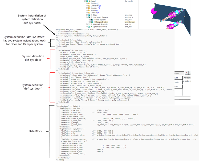
Figure 1.

The door system contains the door along with its hinge joint. The damper system contains the dampers bodies along with their joints with the ground and the door. The door body is passed as an attachment to the damper system to define the joint between the door and the damper.

MDL file:
  • The entire model information is contained within a *BeginMDL - *EndMDL block.
  • The hatchback system (variable name sys_hatch) is instantiated as child of the model and references the definition def_sys_hatch. sys_hatch is called as an instance of the system definition def_sys_hatch.
    • This definition has two system instances: sys_door and sys_damper, which are instances of the system definition def_sys_door and def_sys_damp, respectively.
    • The door body (variable name b_door) is passed as an attachment to the system sys_damper.
  • The data for the entities in the model are within the *BeginContext - *EndContext block and are hierarchical in nature.

Add a System

Use the Systems tool to add systems and assemblies to the model.

  1. From the Assembly ribbon, Arrange tool set, click the System icon.
    The Add System dialog is displayed.
  2. Optional: To change the parent entity in which the new system will be stored, double-click the Parent collector and select a system from the Model Tree.
  3. Specify a label and variable name.
  4. Specify a definition name for the system.
  5. Click OK to close the window or Apply to continue creating entities.
    The system is added to the model.

Edit a System

Clicking on the System in the Project Browser opens a panel, where you can make edits to the selections.

  1. Each system and assembly has a list of attachments that connect it to other systems or assemblies. These are listed on the Attachments tab. You can modify an attachment by highlighting it in the Attachments list and using the entity collector to the right of the list.
    1. Select the Attachments tab.
    2. Click Add.
    3. In the dialog, specify a label and variable name.
    4. Select the attachment entity from the drop-down menu.
    5. Select Single only or Pair or single for Type.
      Note: Certain entities cannot be modeled in pairs so these options may be disabled.
    6. Enter any notes.
  2. Click the Options tab.
    A list of the options belonging to the current system is displayed. An option is used to customize some type of modeling behavior. Options can perform operations such as turning entities on or off, or converting systems from compliant to non-compliant.
  3. Each system has a Compliant option by default. This option can be used to toggle the state of joints within the system. Specify whether to make the system compliant or non-compliant from the drop-down menu.
    Selecting Yes makes all the compliant joints in the system compliant while selecting No makes all compliant joints non-compliant.
  4. Select the Initial Conditions tab.
    1. Enter values in the x, y, and z directions to set the initial translational and rotational velocity of all bodies in the system.
      Note: Initial conditions can be applied to any system in the model. The initial conditions applied to a system are automatically applied to its subsystems. If the initial conditions of a subsystem are set separately, the settings override those of the system above it. Each initial setting that is overridden by a subsystem is listed on the right side of the parent system’s Initial Conditions tab.
  5. Select the System Translation tab.
    If symmetry is on, system symmetry is maintained. If symmetry is off, the entire system moves in the specified direction.
    1. Define a translation direction.
    2. Enter the distance to move the system along the coordinates in the Translation distance text box.
  6. Click the Import/Export tab.
    Note: Systems can be individually imported or exported from/to an .mdl file. You can export the entire system, including the topology information to the file, or you can export only the model properties for reading into another model.
    1. Select the Export radio button.
    2. Browse to select a path and file name and click Save.
    Tip:
    • You can re-export to the same file without opening the browser by clicking Quick Export.
    • Use the Export topology as drop-down menu to specify entity definition statements and definition blocks (that define systems, datasets, templates, etc.).
    • The Property Data options refers to *Set statements that assign values to the entity.

In addition to converting compliant joints, MotionView can turn other entities on or off in a system according to predefined system settings. For example, MotionView can turn off specific entities such as springs or stabilizer bars when the system is made non-compliant.

Note:
  • The Compliant option is applied to all subsystems beneath the current system.
  • The Compliant option can be overridden for individual joints in the Joints panel.
  • Not all joints can be compliant. The rules for converting joints from compliant to non-compliant are built into each model using the MDL language.
  • See *Option() in the MDL Language Reference for more information on creating options.