Create and Edit Analyses
In MotionView, an analysis is a container entity that can contain collections of the loads, motions, and entities that describe the event to be simulated for a model. A model can contain any number of analyses but only one analysis can be active at a given instance. When a model is run in MotionView, a particular analysis is selected and MotionView includes the loads and motions described in the analysis when it submits the model to the solver.
An analysis is represented by the following characteristics:
- An analysis can be added only to the root system Model.
- It can contain any other modeling entities like points, bodies, joints, forces, etc.
- An analysis can have a system as its child entity.
- Only one analysis can be a active at a given instance. The MDL statement that sets an analysis active is *Self-analysis. The Run panel and Export Solver Deck pre-selects the active analysis.
- The analysis takes attachments in a similar way as systems and assemblies.
Similar to an assembly, which is an extended version of systems, the analysis container entity is also extended to have a distributed file approach. However, the extension is contained within the same entity called "Analysis". The analysis container comes in two variations:
Inline Analysis
This refers to the existing style of using the Analysis feature, where the analysis definition and properties are saved inline within the model MDL file.
- In MDL, an inline analysis is created by instantiating a definition using the *Analysis statement that refers to a *DefineAnalysis block.
Distributed Analysis
This refers to the distributed files based analysis, similar to an assembly entity. This type of analysis works on a similar concept as assemblies with some rules and exceptions:
- Distributed analysis refers to a data file and data file subsequently refers to a definition file, which is similar to an assembly entity.
- An assembly can be added to a distributed analysis, but not to an inlined analysis.
- Unlike assemblies, a placeholder for a distributed analysis is not available.
- A distributed analysis has a ALLOWED_MODEL_TYPE attribute that can be used to restrict the application of the analysis for a particular type of model.
- In MDL, a distributed analysis is instantiated using the *BeginAnalysis block. This block has a *DataInclude statement that refers to a data file. The data file contains a *BeginAnalysisDataFile block that has *DefinitionInclude that refers to a definition file. The definition file holds *BeginDefinitionFile that contains the *DefineAnalysis block. This structure is consistent with that of the assembly entity.
Example
The following simple example model demonstrates the concept of an analysis. This model is available at ~hw_install/demos/mv_hv_hg/modeling/container_entities/system_analysis/door.mdl. The model has been arranged into a system called hatchback system, which in turn has two child systems; the door system and the damper system. The images below show a simplified model of a hatchback door of a car with the model MDL file shown alongside.
One analysis to be preformed on the above model is a kinematic analysis, which is accomplished by adding a motion to the hinge joint in the door system.
Another analysis is a dynamic analysis, which is accomplished by applying a force at the end of the door. These two events are exclusive. For example, the motion of the hinge joint is not applied when the force is applied and vice-versa.
- The entire model information is contained within a *BeginMDL - *EndMDL block in the door.mdl (model file).
- Apart from the two system instances and their definition block, the model
contains an *Analysis statement that instantiates the
kinematic analysis (ana_kin). This analysis instance
refers to the analysis definition (def_ana_kin) within
the *DefineAnalysis block in the model file.
- The door hinge joint from the door system is passed as an attachment to the analysis. A motion is defined that uses this attachment.
- The data related to the motion is within the *BeginContext
(ana_kin) block.
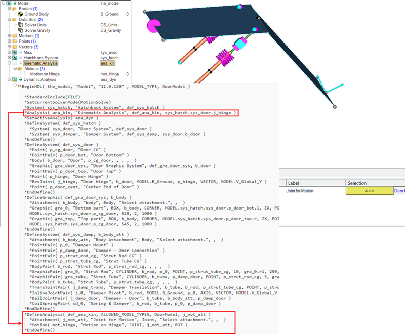
Figure 1.
- The model file also contains a *BeginAnalysis block that
instantiates the dynamic analysis.
- This block refers to the data file (dyn_data.mdl) which in turn refers to the definition file (dyn_def.mdl).
- The door body and the center end point at the door are passed as attachments to this analysis. A force entity is defined that uses these attachments.
- The force data is contained in the data file.
- The MDL structure is similar to that of the assembly. The data is
contained within *BeginAnalysisDataFile. The
analysis definition block *DefineAnalysis in the
definition file is contained within
*BeginAnalysisDataFile.
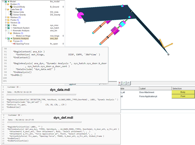
Figure 2.
- The *SetActiveAnalysis statement controls which analysis is active.
Add an Analysis
Use the Analysis tool to add an analysis to the model.
Adding Attachments to an Analysis
Each analysis has a list of attachments that connect it to other systems or assemblies. These are listed on the Attachments tab. You can modify an attachment by highlighting it in the attachments list and using the entity collector to the right of the list.
- To specify a tag for the attachment, click in the Attachment Tag field and enter in a tag string.
- Delete an attachment by selecting it from the list and clicking Delete.
- Modify an attachment's properties by selecting it from the list and clicking Edit.
Adding an Analysis to the Current Model Using an Existing Data File
Edit an Analyses
Modify attachments, set initial conditions, define options, and import/export the analysis.
Export an Inline Analysis
Analyses can be individually exported to an .mdl file by clicking the Import/Export tab on the panel. You can export the entire analysis, including the topology information to the file, or you can export only the model properties for reading into another model. Only inline analyses can be exported to a definition file.
- Re-export to the same file without opening the browser by clicking Quick Export.
- Use the Export topology as: drop-down menu to specify entity definition statements and definition blocks (that define systems, datasets, templates, etc.).
- The Property Data options refers to *Set statements that assign values to the entity.
Import a System to an Analysis from a File
Systems can be imported into an Analysis from an .mdl file through the Import/Export tab on the panel.
Adding an Inline Analysis to the Current Model
Adding a New Analysis Data File Which References an Existing Definition File
Adding a New Analysis Data File and a New Definition File
Defining the Initial Conditions of an Analysis
The Initial Conditions tab on the Analysis panel enables you to specify initial conditions for analyses.
Defining the Options of an Analysis
An option is used to customize an entity definition within an analysis. Options can perform operations such as turning entities on or off, or converting joints in an analysis from compliant to non-compliant.
When you select the Options tab on the Analysis panel, a list of the options belonging to the current analysis is displayed. Each analysis has a compliant option by default. This option can be used to toggle the state of joints within the analysis. The joint or bushing within the analysis should be modeled within an *if(Op_Compliant == "Yes") loop in the MDL language using a text editor.
Defining the Translation of an Analysis
The System Translation tab on the Analysis panel allows you to change the position of an analysis within a model. If symmetry is on, analysis symmetry is maintained. If symmetry is off, the entire analysis moves in the specified direction.