User Signals for Altair Driver
This system contains five signals which are used by driver for multiple use cases.
These signals can be accessed on the Altair Driver panel in the User Signals tab.
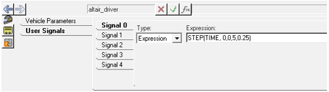
Figure 1.
Figure 1.
- Open Loop Signals or User defined
signals.
$------------------OPEN_LOOP_STEER
[OPEN_LOOP_MOTIONVIEW]
TAG = 'OPENLOOP'
TYPE = 'MOTIONVIEW'
SIGNAL_CHANNEL = 0
This block would link up the solver variable attached as Signal 0 as the throttle signal.
- Open loop signals – expressions through ADF.User can directly override the solver variable through ADF file.
$------------------OPEN_LOOP_STEER
[OPEN_LOOP_EXPRESSION]
TAG = 'OPENLOOP'
TYPE = 'EXPRESSION'
SIGNAL_CHANNEL = 1
EXPRESSION = ‘SIN(TIME/2)’
$-----------------------------------------------------
This block would override the solver variable attached as Signal 1 to produce a sinusoid of amplitude 1 (angle model units) and frequency of 2 Hz.
- The above two methods are also used to generate control signals for feedback signals.
$-------------------------------------FOLLOW_PATH
[LONG_PID_CONTROLLER]
TAG             = 'PID'
TYPE             = 'FOLLOW_VELOCITY'
DEMAND_SIGNAL       = 'DEMAND_SPEED'
$------------------Read from demand signal block
KP              = 100
KD             = 20
KI             = 10
$--------------------------------------DEMAND_SPEED
[DEMAND_SPEED]
TYPE = 'EXPRESSION'
SIGNAL_CHANNEL = 2
EXPRESSION = '10 + 5*SIN(TIME/3)'
These blocks are used to instantiate feedback traction controller which follows a control signal ’10 + 5*SIN (TIME/ 3)’.