Driver Graphical User Interface
-
Click on the Altair driver analysis to bring up the Altair driver graphical
user interface.
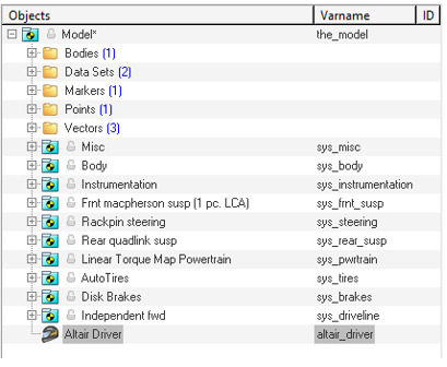
Figure 1.The corresponding panel is displayed.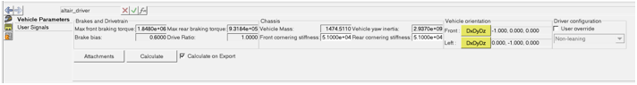
Figure 2. -
Define any MotionView signal that can be used in
the ADF as path profile, velocity profile, etc. in the User
Signals tab.
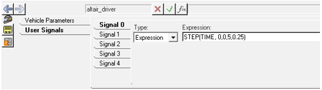
Figure 3. -
Click on the Attachments button to open the Altair
Driver Attachments dialog.
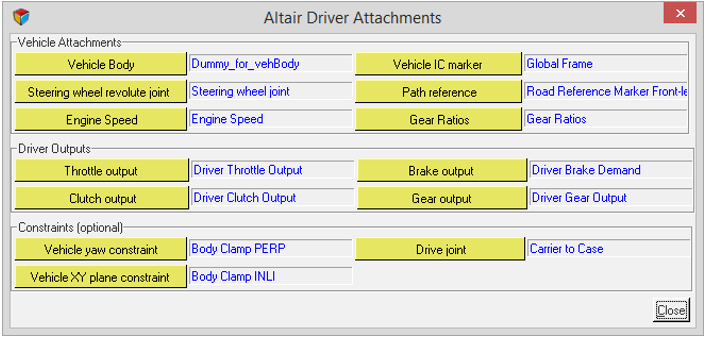
Figure 4.Attachments Vehicle Body *Required
Vehicle body to calculate velocities, accelerations and position of the vehicle. Vehicle IC marker *Required
Marker with respect to whom the initial velocities are specified in the Altair driver file. Steering wheel revolute joint *Required
Steer joint of the vehicle used to lock the joint during static and define motion/torque on for steer controller outputs. Path reference *Required
Marker with respect to whom the user defined path, if any, is resolved. Engine Speed *Required (IC engine powertrain)
Solver variable from the powertrain system that gives engine speed. Present only if IC engine is selected for the model.
Resolved with the Dummy variable in powertrain system in case of linear torque map powertrain.
Gear Ratios *Required (IC engine powertrain)
Curve that informs driver about the gear ratios of the gear box if any. Present only if IC engine is selected for the model.
Resolved with the Dummy variable in a powertrain system in the case of a linear torque map powertrain.X(Gear) Y(Ratio) 0 0.00 (oth gear is ignored) 1 4.7 2 3 Throttle output *Required
Solver variable in vehicle model used by Altair driver to populate throttle output. Brake output *Required
Solver variable in vehicle model used by Altair driver to populate brake output. Clutch output *Required (IC engine powertrain)
Solver variable in vehicle model used by Altair driver to populate clutch output. Present only if IC engine is selected for the model.
Resolved with the Dummy variable in powertrain system in case of linear torque map powertrain.
In case it is not needed, if can be resolved to any unused solver variable.
Gear output *Required (IC engine powertrain)
Solver variable in vehicle model used by Altair driver to populate gear output. Present only if IC engine is selected for the model.
Resolved with the Dummy variable in powertrain system in case of linear torque map powertrain.
In case it is not needed, if can be resolved to any unused solver variable.
Vehicle yaw constraint *Optional
Perpendicular axes joint between vehicle body and the ground body. Used to constrain the vehicle from yawing while solving static.
The constraint is deactivated after solving Static.
Vehicle XY plane constraint *Optional
Inline joint between vehicle body and ground body. Aligning z axes of both ground and body. Used to constrain the vehicle from translating along XY plane while solving static.
The constraint is deactivated after solving Static.
Drive joint *Optional
Revolute joint between drive shaft and engine body fixed to the vehicle. Used to lock the differential while solving static.
The constraint is deactivated after solving Static.
-
Click on the vehicle parameters tab to provide vehicle information required by
the closed loop controllers.
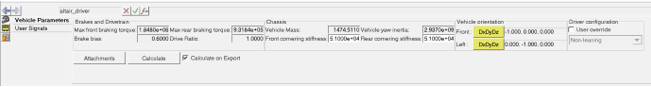
Figure 5.Vehicle parameters are needed by feedforward controllers to predict the states of the vehicle ahead in time. These vehicle parameters are required only if one of the feedforward controllers are being used. The internal models are anyways approximate and therefore, precise values are not required. Tire related vehicle parameters are retrieved inside of the solver during simulation.Chassis Vehicle Mass (kg) Total mass of the Vehicle. Used by the Feedforward traction controller.
Vehicle Yaw Inertia (kg m2) Inertia of the Vehicle about the Z-axis. Used by the Feedforward traction controller.
Front cornering stiffness Average cornering stiffness of the front set of tires. Used by the Feedforward traction controller.
Rear cornering stiffness Average cornering stiffness of the rear set of tires. Used by the Feedforward traction controller.
Brakes and Drivetrain Brake bias Front to Rear. 0 is 100% front, 1 is 100% rear. Used by the Feedforward traction controller.
Max front braking torque (N) Maximum braking torque produced at the front axle of the vehicle. Used by the Feedforward traction controller.
Max reat braking torque (N) Maximum braking torque produced at the reat axle of the vehicle. Used by the Feedforward traction controller.
Drive ratio Coupler ratio between drive coupler output and input shafts. Note that drive ratio is 3.7 in case of default RWD model and 1 in case of default FWD model. Used by the Feedforward traction controller.
Vehicle Orientation Front/Left Vehicle orientation has Front and Left vectors defined according to the orientation of the vehicle. Used as reference for Altair Driver generated paths like Straight, Constant radius, Single lane change, Double lane change etc.
Used by feedforward steering controller.
Driver Configuration User override To override the default driver configuration of the vehicle.
Default driver configuration is automatically set based on number of wheels (AutoTires): Leaning for vehicles with two wheels and “Non-leaning” for those with more.
In cases where the vehicle has more than two wheels, but the vehicle body is expected to lean, you need to click user override and switch the configuration to Leaning.Leaning/Non-leaning Set the Driver configuration to “Non-leaning” or “Leaning”. According to this selection, you can add leaning or non-leaning events to the model.
The leaning events uses leaning steering controllers (2-wheeler) and the non-leaning events uses non-leaning steering controllers (cars and trucks) in the solver. You can change the default selection by checking User override and setting the selection, ex. for leaning three-wheelers.Note: If you change the driver configuration, the existing events in the model need to be added again.