Datasets
Vehicle Parameters
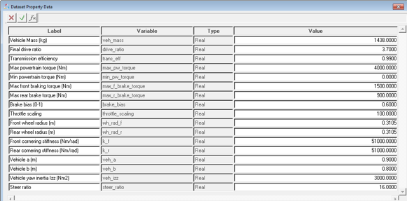
Figure 1.
| Parameter | Type | Range | Comments |
|---|---|---|---|
| Vehicle Mass | Real | Value>0 | |
| Final drive ratio | Real | Value>0 | Coupler ratio between drive coupler output and input shafts. Note that drive ratio is 3.7 in case of default RWD model and 1 in case of default FWD model. This value is not parameterized. |
| Transmission efficiency | Real | Value>0 | Input omega/(output omega*Drive ratio). |
| Drive type | Option | Value = FWD or RWD | Four wheel drive not allowed for advanced driver. |
| Max. powertrain torque | Real | Value > 0 | Torque produced by the powertrain at the input shaft of the differential at
100% throttle. *Required only for vehicle models without CSE powertrain. Driver can directly query CSE powertrain. |
| Min. Powertrain torque | Real | Torque produced by the powertrain at the input shaft of the differential at
0% throttle. *Required only for vehicle models without CSE powertrain. Driver can directly query CSE powertrain. |
|
| Maximum front braking torque | Real | Value>0 | Maximum braking torque on front axle at 100. |
| Maximum rear braking torque | Real | Value>0 | Maximum braking torque on rear axle. |
| Brake bias | Real | 0<Value<1 | Front to Rear. 0 is 100% front, 1 is 100% rear. |
| Front wheel radius | Real | Value>0 | Loaded radius |
| Rear wheel radius | Real | Value>0 | Loaded radius |
| Front cornering stiffness | Real | Value>0 | |
| Rear cornering stiffness | Real | Value>0 | |
| Vehicle a | Real | Value>0 | X component (Vehicle SAE system) of the distance from vehicle front axle to vehicle CG. |
| Vehicle b | Real | Value>0 | (Wheel base - vehicle a) |
| Vehicle yaw inertia | Real | Value>0 | |
| Steer ratio | Real | Value>0 | Ratio of steering wheel input to tire motion (toe). |
Analysis Settings
| Parameter | Type | Range | Comments |
|---|---|---|---|
| Altair Driver file | File | Address of the file path |
Signal Dimensions
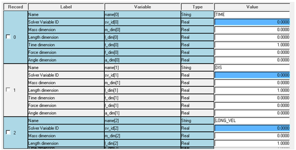
Figure 2.
$Example ADF end conditions block
(END_CONDITIONS)
 {SIGNAL      GROUP   ABS   OPERATOR   VALUE   TOLERANCE   WATCH_TIME}
  LONG_VEL      0      Y      SS        0.0      0.0001       1.50
  ROLL_ANGLE    1      Y      SS        0.0      0.0001       1.50
  PITCH_ANGLE   2      Y      SS        0.0      0.0001       1.50
  YAW_RATE      3      Y      SS        0.0      0.0001       1.50
  CG_Z          4      Y      SS        0.0      0.0001       1.50
$------------------------------------------------------------------------------------------------------------------
Using this block in ADF and signals dimension dataset, Driver will know the appropriate conversion factors for each and every value.
Control States
| MDL Statements | |
|---|---|
|
|
| gse_advanced_driver | Variable name of the driver cse. |
| “CSE Advanced Driver” | Label |
| 6 | Number of outputs. |
| sa_u_advanced_driver | Solver array with input signals. |
| Driver resizes the state array and sets initial conditions of the states internally. Hence, the state IC array should not be provided. | |
|
|
| USER | Indicates that Motionsolve should look outside its dll’s for the entry point. |
| USER({sa_par.idstring}) | Function call with par[0] = Array ID with vehicle parameters |
|
|
| 1 | The number of states are by default set to 1. |
|
|
| Msautoutils | Looks for this dll first in the current directory and then in MotionSolve installation. |
|
|
| SCRIPT_DRIVER | Entry point function name. |
Motions
| Steering wheel motion | Driver computes the required steering angle and applies motion to the steering wheel joint. |
| Differential motion | Required to lock the differential during static (present only if drive joint attachment is resolved in the Driver attachment dialog). |
Forces
| Steering torque | Driver computes the required steering torque and applies torque to the steering wheel joint. |
Sensor
| Maneuver switch | Switch to end one maneuver and start next maneuver. Sensor uses a sensor subroutine to monitor the signals and end conditions associated with the signal to actuate the switch. |
Solver Arrays
These solver arrays are parameterized to data sets or attachments and provide several pieces of vehicle information to the Solver.
| Mass Info Array |
|
| Brake Info Array |
|
| Tire Info Array |
|
| Powertrain Info Array |
|
| Drive Train Info Array |
|
| Driver Info |
|
| Bicycle Model Info Array |
|
| Vehicle Parameters Array |
|
| Sensor Mass Dimension array (Using signal dimensions dataset table) |
|
| Sensor Length Dimension array (Using signal dimensions dataset table) |
|
| Sensor Time Dimension array (Using signal dimensions dataset table) |
|
| Sensor Force Dimension array (Using signal dimensions dataset table) |
|
| Sensor Angle Dimension array (Using signal dimensions dataset table) |
|
| Sensor Label Dimension array (Using signal dimensions dataset table) |
|
| Sensor Solver variable ID array (Using signal dimensions dataset table) |
|
| Sensor Master array (Using signal dimensions dataset table) |
|
| Input Signal Array (GSE, U type) |
|
| Motion array |
|
| Force array |
|
| Joint array |
|
| Jprim array |
|
| Sensor array |
|
| Output Signal array |
|
| Solver Diff array |
|
| Control Entities Array |
|
Solver Diff
| Steering angle differentiation | `ARYVAL({gse_msautoDriver_1.y_array.idstring},1)` |
| Throttle | `ARYVAL({gse_msautoDriver_1.y_array.idstring},2)` |
Solver Variables
| Driver Steer output | `ARYVAL({gse_msautoDriver_1.y_array.idstring},1)` |
| Driver throttle output | `ARYVAL({gse_msautoDriver_1.y_array.idstring},2)` |
| Driver brake output | `ARYVAL({gse_msautoDriver_1.y_array.idstring},3)` |
| Driver gear output | `ARYVAL({gse_msautoDriver_1.y_array.idstring},4)` |
| Driver clutch output | `ARYVAL({gse_msautoDriver_1.y_array.idstring},5)` |
| Distance traveled | `ARYVAL({gse_msautoDriver_1.y_array.idstring},6)` |
| Demand traction signal | `ARYVAL({gse_msautoDriver_1.y_array.idstring},8)` |
| Steer torque | `ARYVAL({gse_msautoDriver_1.y_array.idstring},9)` |
| Simulation Time | TIME |
| Engine speed | `VARVAL(<Engine speed attachment solver
variable>)` |
| Longitudinal velocity wrt to gyro | -VX ( <Gyro fixed marker> , <Ground body CM marker> , < Gyro fixed marker > ) |
| Lateral velocity wrt gyro | VY ( <Gyro fixed marker> , <Ground body CM marker> , < Gyro fixed marker > ) |
| Yaw rate wrt gyro | WZ ( <Gyro fixed marker> , <Ground body CM marker> , < Gyro fixed marker > ) |
| Longitudinal acceleration wrt gyro | -ACCX( <Gyro fixed marker> , <Ground body CM marker> , < Gyro fixed marker > ) |
| Lateral acceleration wrt gyro | -ACCY( <Gyro fixed marker> , <Ground body CM marker> , < Gyro fixed marker > ) |
| Longitudinal displacement | DX ( <Vehicle Body>) |
| Lateral displacement | DY ( <Vehicle Body>) |
| Vertical displacement | DZ ( <Vehicle Body>) |
| Yaw angle | AZ(<Vehicle Body>) |
| Roll Angle | ROLL(<Vehicle Body>) |
| Pitch Angle | PITCH(<Vehicle Body>) |
| Roll Rate | WX(<Vehicle Body>, <Ground Body>, <Vehicle Body>) |
| Pitch Rate | WY(<Vehicle Body>, <Ground Body>, <Vehicle Body>) |
| User signal 0 | User defined in Altair Driver panel (signal_0) |
| User signal 1 | User defined in Altair Driver panel (signal_1) |
| User signal 2 | User defined in Altair Driver panel (signal_2) |
| User signal 3 | User defined in Altair Driver panel (signal_3) |
| User signal 4 | User defined in Altair Driver panel (signal_4) |
| Steering wheel error derivative | DIF1(<Steering angle solver diff>)' |
| Steering wheel angle on vehicle | -AZ(<Steering wheel joint i body>,<Steering wheel joint j body>)` |
| Demand traction signal derivative | DIF1(<Demand traction signal solver diff>)` |
Template
Introduces the differential lock motion if the drive joint attachment of driver is unresolved.
{ driveJt = {PARENT.ds_vehicle_params.int_jdrive_ID.value} }
{if (driveJt != 0 )}
  <Motion_Joint
     id                  = "{abs( id - driveJt + 1)}"
     label               = "Differential motion"
     full_label          = "Model-Altair Driver-Differential motion"
     type                = "CONSTANT"
     val_type            = "D"
     q                   = "0."
     joint_id            = "{PARENT.ds_vehicle_params.int_jdrive_ID.value}"
     motion_type         = "R"
  />1
    {endif}
Sensors
| Maneuver switch | Switch to end one maneuver and start next maneuver. Sensor uses a sensor subroutine to monitor the signals and end conditions associated with the signal to actuate the switch. |
System Gyro
Gyro (short form for gyroscope) is used to calculate the roll and pitch corrected velocities and displacements for the driver inputs.
| Gyro body | Body to make attachments with the vehicle body. |
| Gyro body CG to gyro X dis CG to gyro Y dis CG to gyro Z dis |
Dataset containing the position information of the gyro. Gyro X - Vehicle CG X Gyro Y - Vehicle CG Y Gyro Z - Vehicle CG Z |
| Gyro parallel axes joint Gyro hookes joint |
Parallel axes joint between ground body and gyro body. Aligns Global Z with
gyroCM Z axis. Aligns cross pins of the Gyro X and Gyro Y with vehicle X and vehicle Y using a universal joint. |
| Gyro fixed marker | Marker fixed to the gyro body. |
| Gyro location | CGf location of the gyro body. |