Test
The Test component is required to define the options in the Test Properties section.
You can add any number of tests that stroke the spring to determine the spring’s force-deflection curve and stiffness, either with the shackle (slipper end) as if the spring was installed in the vehicle or without the shackle (SAE J510). The inputs that describe a test are described below.
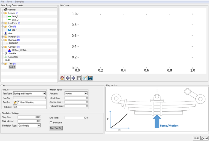
Figure 1. Test Component in Leaf Builder
Inputs
- Test Type
- There are two test types: “Spring and Shackle” and “Spring only (SAE J510)”.
- Spring and Shackle
- Test Type: Spring and Shackle strokes the spring as mounted in the
vehicle.
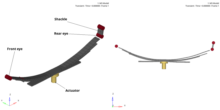
Figure 2. - Spring Only (SAE J510)
- Test type “Spring Only” strokes the spring without the shackle following the SAE J510 guidelines to generate the spring’s characteristic Force vs Deflection curve. For this test the spring eyes contact a flat plate and a displacement is input via a loading block on the bottom of the spring. In an actual test the spring is inverted and pushed downward into a plate. In the Leaf Spring Builder, gravity is directed in the +Z direction effectively inverting the spring and the centers of the spring eyes or the spring tips for slipper ends are constrained by in-plane joints.
- The test has four phases:
- Relax the spring to its free position.
- Move the spring from free position to curb position over time = 0 to time = End Time / 3.
- Move from curb position to design position over time = End Time / 3 to time = End Time * 2/3.
- Move from design position to metal-metal position from time = End Time * 2/3 to time = End Time.
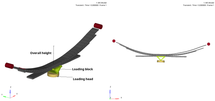
Figure 3.
Spring and Shackle - Force/Motion Inputs
- Actuator
- Select Force or Motion to determine how the input applied to the spring.
- Offset Force/Displacement
- Enter the offset force or displacement from which the test begins. The offset is relative to initial load or position of spring as built.
- Jounce Force/Displacement
- Enter the increment of force or displacement relative to the initial force of displacement for jounce. The sum of the offset force and jounce force give the maximum force applied to the spring, if the actuator is force. Likewise, the sum of the offset displacement and jounce displacement give the maximum displacement applied to the spring, if the actuator is motion.
- Rebound Force/Displacement
- Enter the decrement (positive value) of force or displacement relative to the offset force or displacement for rebound. For a force actuator, the difference between the offset force and rebound force gives the minimum force applied to the spring. For example, if the initial force is 1000 N and the rebound force is 1000 N, then the minimum force in the test is zero (free position). For a motion actuator, the difference between the offset displacement and rebound displacements gives the minimum spring displacement.
Spring-only (SAE J510) - Motion Inputs
Only motion inputs are supported for the Spring Only (SAE J510) test.- Curb
- Enter the increment of spring displacement from the initial spring position to curb position.
- Design
- Enter the increment of spring displacement from curb position to design position.
- Metal-Metal
- Enter the increment of spring displacement from design position to metal-metal position.
The total spring displacement from the initial position is sum of the curb, design, and metal-metal values.
Simulation Settings
- Print Interval
- Enter the time between output steps. The end time divided by the print interval gives the number of outputs steps.
- Step Size
- Enter the time between solution steps. The step size must not be greater than the print interval.
- Simulation Type
- Select Quasi-static or Transient. Quasi-static simulation removes inertia and damping forces. Transient simulation includes damping and inertia forces. It is recommended that you select Quasi-static. If there are problems obtaining a solution, then switch to transient. When using transient simulations, consider using larger end times to slow the rate of change of spring deflection to reduce inertia and damping forces.
- End Time
- Enter the end time of the simulation. Simulations start at time=0, hence the end time is also the duration of the simulation.
- Build Leaf
- Check the build leaf box to build the leaf spring before running the test. You should check the box if you have changed the spring tag that defines if the leaf spring that is loaded in the Leaf Builder has to be built when the Run Test Rig button is clicked.
- Run Test Rig
- Click the Run button to run the simulated leaf spring test.
Test Block for Leaf Property File (*lpf)
The [TEST_BLOCK] in the leaf property file stores the information for all the tests defined in a session. The [TEST_BLOCK] contains one sub-block for each test defined. For example, see subblock (TEST_1) below and note that “TEST_1” is the name of the test as it appears in the Leaf Spring Builder.$----------------------------TEST_RIG
[TEST_RIG]
(TEST_1)
BUILDLEAF = 'FALSE'
CURB = 0.0
DESIGN = 0.0
DIRECTORY = 'C:\USERS\DESKTOP'
ENDTIME = 10.0
FORCEJOUNCE = 0.0
FORCEOFFSET = 0.0
FORCEREBOUND = 0.0
METALTOMETAL = 0.0
MOTIONJOUNCE = 0.0
MOTIONOFFSET = 0.0
MOTIONREBOUND = 0.0
OPTION = 'MOTION'
OUTPUTFILELABEL = 'TEST_'
PRINTINTERVAL = 0.01
RUNNO = 1.0
SIMULATIONTYPE = 'QUASI-STATIC'
STEPSIZE = 0.001
TESTTYPE = 'SPRING AND SHACKLE'
| Attributes | Type | Valid Value | Test Types | Description |
|---|---|---|---|---|
| TESTTYPE | String | ‘TRUE’, 'FALSE' |
- | Type of test to run (in other words, with the spring and shackle or with the spring only). See above. |
| CURB | Real | > 0.0 | Spring only (SAE J510) | Increment of spring displacement at the axle from the free position to curb position. Valid for spring only (SAE J510) test type. |
| DESIGN | Real | > 0.0 | Spring only (SAE J510) | Increment of spring displacement from curb to design position. |
| METALTOMETAL | Real | > 0.0 | Spring only (SAE J510) | Increment of spring displacement from design position to metal to metal position. |
| OPTION | 'MOTION', 'FORCE' | Spring and Shackle | Apply input to the spring by fixing the motion or force. | |
| FORCEOFFSET | Real | > 0.0 | Spring and Shackle | Increment of force from input position. |
| FORCEJOUNCE | Real | > 0.0 | Spring and Shackle | Increment of force from force-offset to jounce. |
| FORCEREBOUND | Real | > 0.0 | Spring and Shackle | Decrement of force from force-offset to rebound. |
| MOTIONOFFSET | Real | > 0.0 | Spring and Shackle | Increment of spring displacement from input position. |
| MOTIONJOUNCE | Real | > 0.0 | Spring and Shackle | Increment of spring displacement from offset position to jounce position. |
| MOTIONREBOUND | Real | > 0.0 | Spring and Shackle | Decrement of spring displacement from offset position to rebound position. |
| BUILDLEAF | String | 'TRUE', 'FALSE' | All | 'True' builds the spring before executing the test. |
| ENDTIME | Real | > 0.0 | All | Duration of the simulated test. |
| PRINTINTERVAL | Real | > STEPSIZE | All | Output step size (end time / print interval = number of solution steps in output files). |
| STEPSIZE | Real | < PRINTINTERVAL | All | Solution step size. |
| DIRECTORY | String | Directory where you have write-privileges | All | Directory where test input and output files are written. |
| OUPUTFILELABEL | String | No special characters or blanks | All | Root name for test input and output files. |
| RUNNO | Integer | Integer value >=0 | All | Number of times test has been run. |