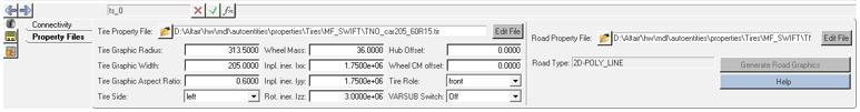
The AutoTire panel is shown in the following image. Figure 1.
Auto Tire- Property Files Tab
The Property Files tab has two sections: Tire Property File and Road Property File. For
tire interface, the tire parameters and the properties are set by a Tire Property File with
the extension (.tir/.tpf), while the road
interface is described by a Road Property File with the extension
(.rdf/.crg/.rgr). Both of
these property files are in the TeimOrbit file format. The parameters of the AutoTire
Properties tab and their significance is explained below:
Tire Property File
Parameter
Description
Tire Property File
Browse and select the required file.
Edit File
Edit the file and save the edited file.
Tire Graphic Radius
Distance between the WC and the contact point of tire in unloaded
conditions.
Tire Graphic Width
Section width of the tire.
Tire Graphic Aspect Ratio
Describes the sidewall height as a percentage of the tire section
width.
Tire Side
Defines the left or right side of the tire.
Wheel Mass
The meaning of wheel mass changes with a tire model.
Fiala, Simplified durability tire
Mass of rim + Mass of Tire
MF-Tyre, MF-SWIFT
Mass of the rim + Mass of tire
‘Mass of tire’ should include the tire belt mass which can
be read from Tire property file (INERTIA block) or it can be
read from MotionSolve log file.
FTire
Mass of the rim + Mass of ‘rim-fixed’ tire
parts
Or
Mass of the rim + Mass of the tire – Mass of
the ‘free’ tire parts
rim-fixed tire parts are not accounted in FTire model, only
‘free’ tire mass is accounted. These masses can be read from the
tire property file or can be read from the MotionSolve log
file.
CDTire
Mass of the rim + Mass of ‘rim-fixed’ tire
parts
Or
Mass of the rim + Mass of the tire – Mass of
the ‘free’ tire parts
rim-fixed tire parts are not accounted in the CDTire model,
only ‘free’ tire mass is accounted. These masses can be read
from the tire property file or can be read from the CDTire log
file.
Inpl.Iner.Ixx, Inpl.Iner.Iyy
Moment of Inertia of the wheel in the wheel plane.
Adjust the wheel
inertia per the tire model by including the inertias of tire fixed parts
that are not accounted for in the tire models.
Rot.Iner.Izz
Moment of inertia of the wheel about the spin axis.
Adjust the wheel
inertia by including or excluding the inertias of tire parts that are
accounted for or not accounted for in the tire models.
Hub Offset
Defines the offset of Hub graphic center from the wheel center.
Wheel CM offset
Defines the wheel part CM offset from the wheel center.
Tire Role
Defines tire function: front or rear.
VARSUB Switch
Activates the solver variables that contains the tire’s states. This
option can be used for control prototyping.
Road Property File
Parameter
Description
Road Property File
Property File option is used to browse and select the required road
property file.
Edit File
Edit file button is used to edit the road property file and save the
edited file.
Method
Defines the road model type.
Road Type
Defines the type of road.
Function Name
Name of the function being called by Solver.
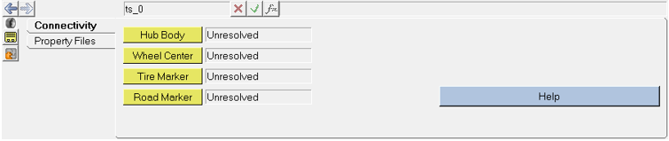
Auto Tire- Connectivity Tab
Use the Hub Body, Wheel Centre, Tire Marker and Road Marker collector buttons in the
Connectivity tab to define the tire interface. Figure 2.
Connection
Significance
Hub Body
The wheel body on which the tire forces act.
Wheel Center
The point corresponding to the wheel center.
Tire Marker
The tire marker determines the direction in which the tire forces
act.
Road Marker
The road marker, is the marker with respect to which the road is positioned
and oriented for the simulation.