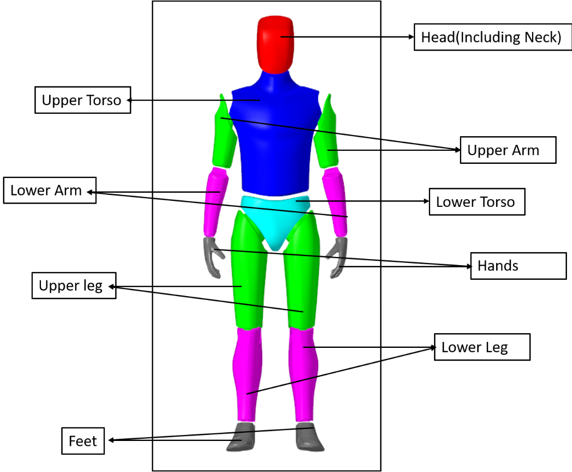
The AutoRider models the mass and inertia of a human body and includes graphics for the
human body.
The AutoRider includes controls for setting the mass and dimension of a human body and for
changing the angles in key joints like the knee and hip. Changing the angles in joints
allows you to position the rider in many postures like standing, kneeling, or sitting.
The AutoRider is not flexible: the bodies comprising the model and the joints connecting
the bodies are rigid. Figure 1.
The mass and dimensions of the AutoRider can be varied based on the modeling
requirements.
Add an AutoRider to a Model
The following steps
outline how to add an AutoRider to the model:
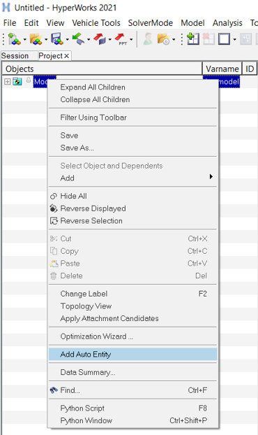
Right-click on the Model in the Project Browser and click
Add Auto Entity. Figure 2.
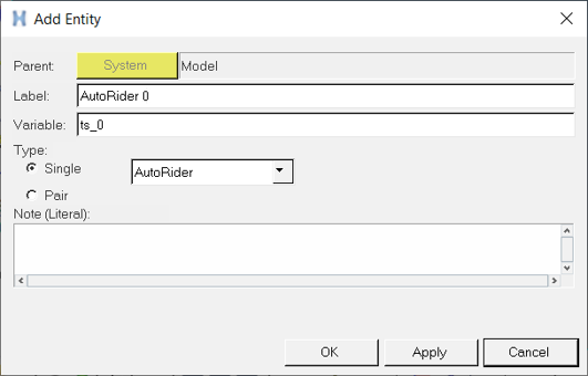
The Add Auto Entity dialog is displayed. Figure 3.
OK
Applies the selected type and closes the window.
Apply
Adds the Auto Entity without closing the window.
Cancel
Exits the Auto Entity dialog.
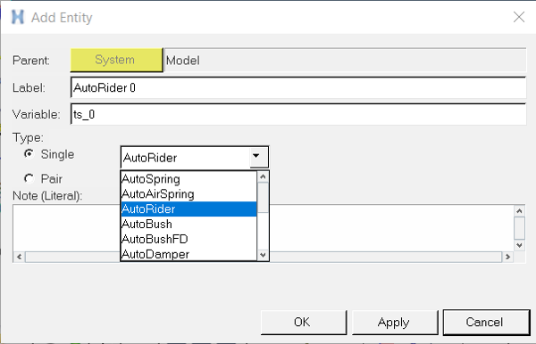
Select the AutoRider from the drop-down menu. Figure 4.
Click OK.
The AutoRider Entity is added to the Project Browser.
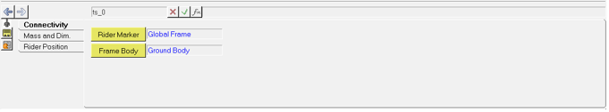
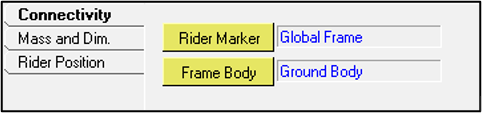
The AutoRider panel is displayed in the panel area. Figure 5.
Resolve the Rider Marker and Frame Body attachments to locate the AutoRider. Figure 6.
Reference
Description
Rider Marker
Reference marker to locate the AutoRider, provides an initial frame of
reference.
Frame Body
To fix the AutoRider to the vehicle body.
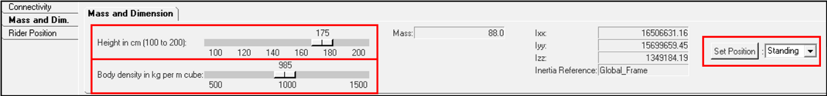
Adjust the AutoRider Mass and Dimensions
Figure 7.
Parameter
Description
Height
Input for the AutoRider height. Height can only vary from 100 – 200 cm. You
can use the slider to vary the height.
Body Density
Input for AutoRider body density. Body density can only vary from 500 – 1500
kg per meter cube. You can use the slider to vary the body density.
Mass
The mass of the AutoRider based on the height and body density value. Unit is
the same as model units.
Ixx, Iyy, Izz
The moment inertia values of the AutoRider based on the height and body
density value. Unit is the same as model units.
Inertia Reference
The reference frame that is being used to calculate mass and inertia
values.
Set Position
Set the pre-defined default positions of the AutoRider. Current options are:
Standing or Sitting.
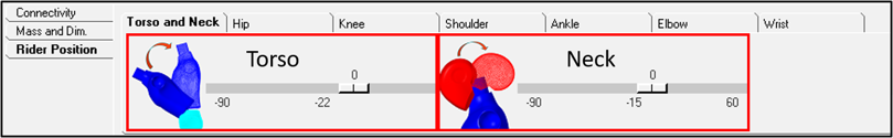
Positioning the AutoRider
Torso and Neck
Figure 8.
Parameter
Description
Torso
Input for the torso angle about y direction. You can use the slider to
vary the angle. Limits of the field can be changed by updating the values of
AY_pel data member in the "MN angles” and "MX angles” data sets.
Neck
Input for the neck angle about y direction. You can use the slider to
vary the angle. Limits of the field can be changed by updating the values of
AY_nec data member in the "MN angles” and "MX angles” data sets.
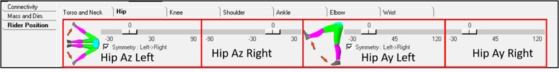
Hip
Figure 9.
Parameter
Description
Hip Az Left
Input for the left hip angle about z direction. You can use the slider
to vary the angle. Limits of the field can be changed by updating the values
of AZ_hip_l data member in the "MN angles” and "MX angles” data sets.
Hip Az Right
Input for the right hip angle about z direction. You can use the slider
to vary the angle. Limits of the field can be changed by updating the values
of AZ_hip_r data member in the "MN angles” and "MX angles” data sets.
Symmetry: L->R
Check the box to mirror the values from left to right. It makes the
right limb angle field read only.
Hip Ay Left
Input for the left hip angle about y direction. You can use the slider
to vary the angle. Limits of the field can be changed by updating the values
of AY_hip_l data member in the "MN angles“ and "MX angles“ data sets.
Hip Ay Right
Input for the right hip angle about y direction. You can use the slider
to vary the angle. Limits of the field can be changed by updating the values
of AY_hip_r data member in the "MN angles“ and "MX angles“ data sets.
Symmetry: L->R
Check the box to mirror the values from left to right. It makes the
right limb angle field read only.
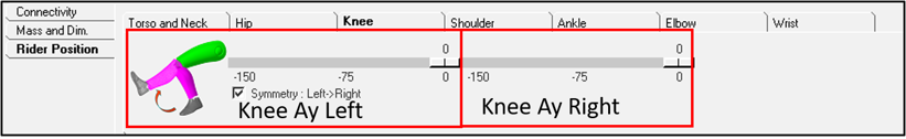
Knee
Figure 10.
Parameters
Description
Knee Ay Left
Input for the left knee angle about y direction. You can use the slider
to vary the angle. Limits of the field can be changed by updating the values
of AY_kne_l data member in the "MN angles“ and "MX angles“ data sets.
Knee Ay Right
Input for the right knee angle about y direction. You can use the
slider to vary the angle. Limits of the field can be changed by updating the
values of AY_kne_r data member in the "MN angles“ and "MX angles“ data sets.
Symmetry: L->R
Check the box to mirror the values from left to right. It makes the
right limb angle field read only.
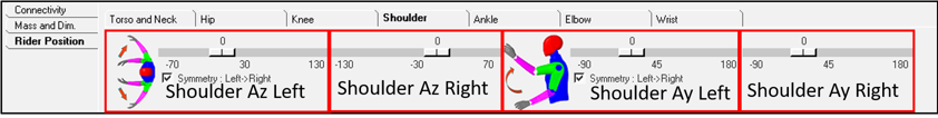
Shoulder
Figure 11.
Parameter
Description
Shoulder Az Left
Input for the left shoulder angle about z direction. You can use the
slider to vary the angle. Limits of the field can be changed by updating the
values of AZ_sho_l data member in the "MN angles“ and "MX angles“ data sets.
Shoulder Az Right
Input for the right shoulder angle about z direction. You can use the
slider to vary the angle. Limits of the field can be changed by updating the
values of AZ_sho_r data member in the "MN angles“ and "MX angles“ data sets.
Symmetry: L->R
Check the box to mirror the values from left to right. It makes the
right limb angle field read only.
Shoulder Ay Left
Input for the left shoulder angle about y direction. You can use the
slider to vary the angle. Limits of the field can be changed by updating the
values of AY_sho_l data member in the "MN angles“ and "MX angles“ data sets.
Shoulder Ay Right
Input for the right shoulder angle about y direction. You can use the
slider to vary the angle. Limits of the field can be changed by updating the
values of AY_sho_r data member in the "MN angles“ and "MX angles“ data sets.
Symmetry: L->R
Check the box to mirror the values from left to right. It makes the
right limb angle field read only.
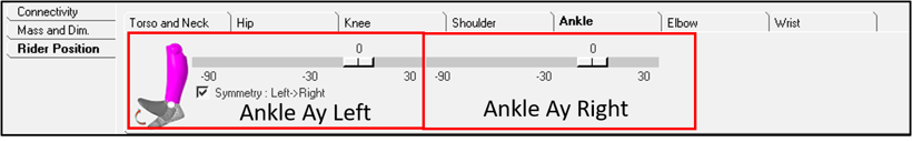
Ankle
Figure 12.
Parameters
Description
Ankle Ay Left
Input for the left ankle angle about y direction. You can use the
slider to vary the angle. Limits of the field can be changed by updating the
values of AY_ank_l data member in the "MN angles“ and "MX angles“ data sets.
Ankle Ay Right
Input for the right ankle angle about y direction. You can use the
slider to vary the angle. Limits of the field can be changed by updating the
values of AY_ank_r data member in the "MN angles“ and "MX angles“ data sets.
Symmetry: L->R
Check the box to mirror the values from left to right. It makes the
right limb angle field read only.
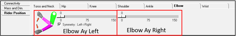
Elbow
Figure 13.
Parameters
Description
Elbow Ay Left
Input for the left elbow angle about y direction. You can use the
slider to vary the angle. Limits of the field can be changed by updating the
values of AY_elb_l data member in the "MN angles“ and "MX angles“ data sets.
Elbow Ay Right
Input for the right elbow angle about y direction. You can use the
slider to vary the angle. Limits of the field can be changed by updating the
values of AY_elb_r data member in the "MN angles“ and "MX angles“ data
sets.
Symmetry: L->R
Check the box to mirror the values from left to right. It makes the
right limb angle field read only.
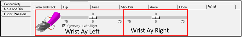
Wrist
Figure 14.
Parameters
Description
Wrist Ay Left
Input for the left wrist angle about y direction. You can use the
slider to vary the angle. Limits of the field can be changed by updating the
values of AY_wri_l data member in the "MN angles“ and "MX angles“ data sets.
Wrist Ay Right
Input for the right wrist angle about y direction. You can use the
slider to vary the angle. Limits of the field can be changed by updating the
values of AY_wri_r data member in the "MN angles“ and "MX angles“ data sets.
Symmetry: L->R
Check the box to mirror the values from left to right. It makes the
right limb angle field read only.
With combinations of the above mentioned controls, one can
position the AutoRider on most vehicles.