AutoReboundStop
The AutoReboundStop entity limits suspension travel in rebound (also known as droop). When the distance between two bodies becomes large, the AutoReboundStop applies a force to pull the bodies together.
$(ALTAIR_HOME)\hw\mdl\autoentities\properties\Bumpers-Rebound
AutoReboundStop Force
- Elastic force or stiffness
- Viscous force or damping
For a linear AutoReboundStop, the elastic force component is calculated using a third order polynomial and for a non-linear AutoReboundStop, the elastic force component is interpolated using the Akima method.
The viscous force component is optional and when defined in the property file, is calculated directly from the damping rate in the property file and resultant instantaneous velocity between the two bodies.
Install Methods
The AutoReboundStop install method is at design position and is used to determine the distance at which the AutoReboundStop force starts acting.
- Impact Length Method
- When the impact length is of value ‘L’, the AutoReboundStop force acts when the distance between the two bodies is less than ‘L’.
- When the Impact Length install method is used, its value is directly used by the
solver to activate the AutoReboundStop force between the two bodies. It is important
to remember that when the Impact Length is less than the initial distance,
dL, the AutoReboundStop force starts acting
immediately.
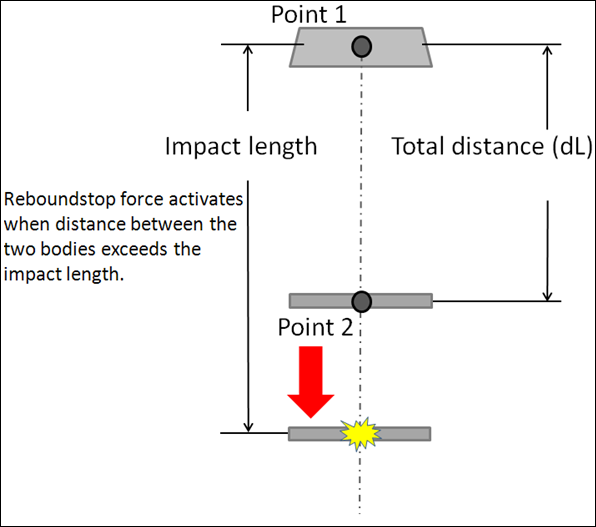
Figure 1. Impact Length Method - Clearance Method
- When the Clearance method is used, the impact distance is calculated
using:
(1) - Where,
(4) 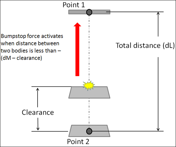
Figure 2.
Connecting an AutoReboundStop
Connections define the two bodies between which the ReboundStop force acts and select two points that are used to calculate the impact distance. The ReboundStop force acts between Body 1 and Body 2. The initial distance is measured between Point 1 and Point 2.
The ReboundStop force is activated when the distance between the two bodies exceeds a certain value. The distance at which the ReboundStop force starts acting is calculated based on the installation method.
-
From the Connectivity tab, select the first body to
connect.
- Click Body 1 and select a body from the modeling window.
- Double click Body 1 and select the required body from the dialog.
- Similarly, select the second body to connect by clicking the Body 2 input collector.
- Select the first point.
- Similarly, select the second point.
- Optional: Check the Output box to add an output request for the ReboundStop resultant displacement, resultant velocity, and resultant force. These outputs are measured between I and J markers.
AutoReboundStop Output Channels
Activating the Output check box adds an output request for the AutoReboundStop resultant displacement, resultant velocity, and resultant force. These outputs are measured between I and J markers.
| Type | Component | Quantity |
|---|---|---|
| REQSUB | RESULT(2) | Distance between I and J markers of the ReboundStop. |
| RESULT(3) | Rate-of-change-of-displacement between I and J markers. | |
| RESULT(4) | ReboundStop force. | |
| RESULT(6) | Global X direction cosine of ReboundStop. | |
| RESULT(7) | Global Y direction cosine of ReboundStop. | |
| RESULT(8) | Global Z direction cosine of ReboundStop. |
AutoReboundStop Properties File
The AutoReboundStop properties are stored in a AutoReboundStop Properties File text file. When you resolve the property file field to a AutoReboundStop property file and submit the model to the solver, the solver reads the AutoReboundStop property file for use during simulation. If the units in the property file differ from the model units, the solver internally converts the AutoReboundStop properties to the model units. The properties file remains unchanged.
The AutoReboundStop properties file contains header, units, and curve blocks. The units block specifies the length, mass, force, time, and angle units employed in the file. The curve block holds a table of displacement against force values for the elastic force component and optionally a velocity against force values for the viscous force component.
$--------------------------------------------------------------------HEADER
[HEADER]
 FILE_TYPE     =  'reb'
 FILE_VERSION  =  4.0
 FILE_FORMAT   =  'ASCII'$
---------------------------------------------------------------------UNITS
[UNITS]
LENGTH =  'mm'
ANGLE  =  'degrees'
FORCE  =  'newton'
MASS   =  'kg'
TIME   =  'second'
$---------------------------------------------------------------------CURVE
[CURVE]
{ disp    force}
0.0   0.0
2.0   1.0
4.0   2.0
6.0   3.0
8.0   4.0
10.0   5.0
20.0   6.0
30.0   7.0
40.0   8.0
50.0   9.0