Import Files
In HyperWorks Desktop various file types can be imported into the selected client.
Import options vary based on the client currently active.
Importing any type of file into HyperWorks Desktop essentially means that the selected file is appended to any file currently open. It does not overwrite/replace the existing file. Therefore, you can use the Import option to open two (or more) files into one window.
Import Models
Import external CAD line and surface data or finite element models. You can also import/merge HyperMesh model files (.hm) into the current model session.
Importing models allows you to import a single or multiple HyperMesh model files into the current HyperMesh session without deleting the current session.
-
Import a model in the following ways:
- From the menu bar, click .
- From the Standard toolbar, click
 (Import
Model).
(Import
Model).
The Import - Model tab opens. -
In the File Selection pane, click
 and select the
file(s) to import.
and select the
file(s) to import.
Remove files from the File Selection pane by clicking
 (Remove
Selection) and
(Remove
Selection) and  (Remove
All).
(Remove
All). -
Define Model Import Options by clicking
 to the left of
Import Options.
to the left of
Import Options.
Model Import Options
Entity management settings defined when importing models.
- Components, Properties, and Materials
-
- Offset ID
- Merge incoming attributes with conflicting IDs into the session, and offsets their IDs. This is the default option for components, properties, and materials for representation entity management.
- Keep Existing Attributes
- Maintain existing in-session entity attributes and incoming conflicting entity IDs.
- Keep Incoming Attributes
- Map incoming entity attributes to the in-session entities.
- Geometry/FE
-
- Keep Both
- Keep both incoming and existing geometry and FE residing in the component with conflicting IDs.
- Keep Existing Only
- Keep existing geometry and FE that resides in the component with conflicting IDs.
- Keep Incoming Only
- Keep incoming geometry and FE that resides in the component with conflicting IDs. This is the default option for geometry and FE for representation entity management.
- Connectors
- When loading connectors along with a HyperMesh binary file, HyperMesh checks for
conflicting spot and bolt connectors.Note: IDs are not considered when checking for conflicting connectors.Define options used to find conflicting connectors by clicking
 , to the right of the
Connector option.
, to the right of the
Connector option.- Tolerance
- Tolerance used to find conflicting connectors. Connector coordinates need to be within a certain tolerance from each other.
- Link Check
- Compare used links by link type, link name, and ID (active by default).
- Thickness Check
- Compare the number of layers (active by default).
- Attribute Check
- Compare the diameter, configuration, solver, and postscripts (inactive by default).
Import FE Models
Import solver input files.
-
Import a model in the following ways:
- From the menu bar, click .
- From the Standard toolbar, click
 (Import
Solver Deck).
(Import
Solver Deck).
The Import - Solver Deck tab opens. -
In the File field, click and select
the file to import.
-
If File Type is set to Custom, click and select
the appropriate reader.
-
Define FE Model Import Options by clicking to the left of Import
Options.
FE Model Import Options
Import options used to determine how FE models are imported.
- Import
- Type of entities to import.
- All
- Import all entities in the selected file.
- Custom
- Select entities to import from the selected file.
- Display
- Turn the display of newly imported load collectors and/or system
collectors on/off. Tip: This option can help improve the performance for FE input models containing large numbers of loads/systems.This option is supported for all import readers. Existing load collectors and system collectors are not affected by this option.
- All
- Turn the display of newly imported load collectors and system collectors on.
- Custom
- Select entities to display.
- Solver options
- Define Solver Import Options import settings by clicking Select Options.
- Create comps
- Method for creating components on import.
- By HM Comments
- Honor the HyperMesh comments $HMNAME COMP, $HMMOVE, and $HMDPRP in the selected file that were created by HyperMesh in any previous export of the model.
- By Property
- Ignore any $HMNAME COMP, $HMMOVE, and $HMDPRP comments that may be in the selected file and automatically create components based on each property in the file. The component name will be the name of the property. The property will also be created and assigned to the component, not the elements. (By Property Hierarchy)
- By 1 Component
- Ignore any $HMNAME COMP, $HMMOVE, and $HMDPRP comments that may be in the selected file and create one component into which all elements in the selected file will be organized. Properties will be created and assigned directly to the elements. (By Component Hierarchy)
- Assign props
- Method for assigning properties to elements on import.
- By HM Comments
- Honor the $HMNAME COMP, $HMMOVE, and $HMDPRP comments and assign properties to elements accordingly. Any elements listed in the $HMDPRP comment will have their property directly assigned, and the remaining elements will take their property from the component.
- On Element
- Honor the $HMNAME COMP and $HMMOVE comments and directly assign properties to all elements based on their card definitions.
- On Component
- Honor the $HMNAME COMP and $HMMOVE comments and leave all
elements to take their property from their
components.Note: Elements can take a property assignment from the component in which it resides, or it can have a property directly assigned to it. Direct assignment takes precedence over component assignment.
- Import as include
- Load and display non-include files as include files.
- Include files
- Method for importing includes.
- Merge
- Import the contents from all include files into the HyperMesh model, but do not maintain their references. When exporting, all entities are written into the master file.
- Preserve
- Preserve data in individual include files along with their references in the master model. Review the contents of individual include files in the Include browser. When exporting, entities are written into the corresponding include files along with their references in the master file.
- Skip
- Do not import data in the include file into HyperMesh. Include references are maintained and written out to the master model during export.
- ID Rules
- Imports ID management rules that were defined in the ID Manager and
exported to a solver deck as an XML block at the end of each Include
file.Restriction: Available when Include files is set to Preserve.
- Create Part Assemblies/Parts
- Create a part hierarchy for each component in the absence of part/part assembly comments, and assign a UID to each newly created part/part assembly.
- FE overwrite
- Overwrite entities that have matching IDs. If checked off, entity IDs are offset to avoid duplicates.
- ID Offset
- Adjust offset settings.
- Display import errors
- Display any errors that occur during the import procedure.
Entity Import Behavior
Overview of how entities are imported.
Assemblies
- Import assembly comment cards (HMASSEM, HMASSEM_IDS) that may exist in the import file and create assemblies per the data in the comment cards.
- Optional additional imports: Components, Elements, Nodes, Connectors
Components
- Import component comment cards (HMNAME COMP, HWCOLOR COMP, HMMOVE, HMDPRP) that may exist in the import file and create component collectors per the data in the comments cards.
- Optional additional imports: Elements, Nodes and Connectors. If both nodes and elements are not imported, then components are imported and created but will contain no elements, that is, empty components. Similar for Connectors.
Load Collector
- Import load collector comment cards (HMNAME LOADCOL, HWCOLOR LOADCOL) that may exist in the import file and create load collectors per the data in the comment cards.
- Optional additional imports: Loads. If loads are not imported then load collectors are imported and created but will contain no loads (that is, empty load collectors)
System Collector
- Import system collector cards (HMNAME SYSTCOL, HWCOLOR SYSTCOL) that may exist in the import file and create system collectors per the data in the comment cards.
- Optional additional imports: Systems. If systems are not imported then system collectors are imported and created but will contain no systems (i.e. empty system collectors).
Vector Collector
- Import vector collector cards (HMNAME VECTORCOLS, HWCOLOR VECTORCOLS ) that may exist in the import file and create vector collectors per the data in the comments cards.
- Optional additional imports: Vectors. If vectors are not imported then vector collectors are imported and created but will contain no vectors (i.e. empty vector collectors).
Beam Section Collector
- Import beam section collector cards (HMNAME BEAMSECTCOLS) that may exist in the import file and create beam section collectors per the data in the comment cards.
- Optional additional imports: BeamSections. If beam sections are not imported then beam section collectors are imported and created but will contain no beam sections (i.e. empty beam section collectors).
MultiBody
- Import multibody comment cards that may exist in the import file and create multibody collectors per the data in the comment cards.
- Optional additional imports: Ellipsoids, MBJoints, MBPlanes. If elipsoids, MBJoints, MBPlanes are not imported, then Multibody collectors are imported and created but will contain no ellipsoids, MBJoints, MBPlanes (i.e. empty multibody collectors).
LoadStep
- Import solver load step card definitions and load step comment cards (HMNAME LOADSTEP) that may exist in the import file and create load step entities per the solver and comment cards data.
Output Block
- Import solver output block card definitions and output block comment cards that may exist in the import file and create output block entities per the solver and comment cards data.
Control Card
- Import solver control card definitions that may exist in the import file and create card entities per the solver cards data.
Property
- Import solver property card definitions and property comment cards (HMNAME PROP, HWCOLOR PROP) that may exist in the import file and create property entities per the solver and comment cards data.
Materials
- Import solver material card definitions and material comments cards (HMNAME MAT, HWCOLOR MAT) that may exist in the import file and create material entities per the solver and comment cards data.
Sets
- Import solver set card definitions and set comment cards (HMSET) that may exist in the import file and create set entities per the solver and comment cards data.
Blocks
- Import solver block card definitions and block comment cards that may exist in the import file and create block entities per the solver and comment cards data.
Tags
- Import solver tag card definitions and tag comment cards (HMTAG) that may exist in the import file and create tag entities per the solver and comment cards data.
Titles
- Import solver title card definitions and title comment cards that may exist in the import file and create title entities per the solver and comment cards data.
Plots
- Import solver plot card definitions and plot comment cards that may exist in the import file and create plot entities per the solver and comment cards data.
- Optional additional imports: Curves
Contact Surface
- Import solver contract surface card definitions and contact surface comment cards that may exist in the import file and create contact surface entities per the solver and comment cards data.
- Optional additional imports: Nodes, Elements
Group
- Import solver group card definitions and group comment cards (Domain) that may exist in the import file and create contact surface entities per the solver and comment cards data.
- Optional additional imports: Nodes, Elements
Sensor
- Import solver sensor card definitions and sensor comment cards that may exist in the import file and create sensor entities per the solver and comment cards data.
Control Volume
- Import solver control volume card definitions and control volume comment cards that may exist in the import file and create control volume entities per the solver and comment cards data.
Node
- Import solver node card definitions that may exist in the import file and create node entities per the solver cards data.
Element
- Import solver element card definitions that may exist in the import file and create the appropriate element config/type entities per the solver cards data.
- Required: Nodes
- Optional additional imports: Assemblies, Components. If components are not imported then all elements will be organized into an "Auto" component.
Connector
- Import master connector file xml data that may exist in the import file and create connector entities per the connector xml data.
- Required: Nodes, Elements, Components
- Optional additional imports: Assemblies
Load
- Import solver load card definitions that may exist in the import file and create the appropriate load config/type entities per the solver cards data.
- Required: Nodes (Forces, Moments, Temperatures)
- Optional additional imports: Load Collectors. If load collectors are not imported then all loads will be organized into an "Auto" load collector
Equation
- Import solver equation card definitions that may exist in the import file and create the appropriate equation entities per the solver cards.
- Required: Nodes
- Optional additional imports: Load Collectors. If load collectors are not imported then all loads will be organized into an "Auto" load collector
System
- Import solver system card definitions that may exist in the import file and create system entities per the solver cards.
- Required: Nodes (For Node Dependent Systems)
- Optional additional imports: System Collectors. If system collectors are not imported then all systems will be organized into an "Auto" system collector.
Vector
- Import solver vector card definitions that may exist in the import file and create vector entities per the solver cards data.
- Required: Nodes (For Node Dependent Systems)
- Optional additional imports: Vector Collectors. If vector collectors are not imported, then all vectors will be organized into an "Auto" vector collector.
BeamSections
- Import beam section comment cards (HMNAME BEAMSECTS) that may exist in the import file and create beam section entities per the comment cards data.
- Optional additional imports: Beam Section Collectors. If beam section collectors are not imported then all beam sections will be organized into an "Auto" beam section collector.
Curve
- Import solver curve card definitions and curve comment cards (HMNAME CURVES, HMCOLOR CURVES, HMCURVE) that may exist in the import file and create HyperMesh curve entities per the solver and comment cards data.
- Optional additional imports: Plots
Ellipsoids
- Import solver ellipsoid card definitions that may exist in the import file and create ellipsoid entities per the solver cards data.
- Optional additional imports: Multibodies. If multibodies are not imported, then all ellipsoids will be organized into an "Auto" multibody collector.
Multibody Planes
- Import solver MB plane card definitons that may exist in the import file and create MB plane entities per the solver cards data.
- Optional additional imports: Multibodies. If multibodies are not imported, then all ellipsoids will be organized into an "Auto" multibody collector.
MultiBody Joints
- Import solver MB joint card definitions that may exist in the import file and create MB joint entities per the solver cards data.
- Optional additional imports: Multibodies. If multibodies are not imported, then all ellipsoids will be organized into an "Auto" multibody collector.
Solver Import Options
Supported solver import options.
Access solver import options by clicking Select Options, next to Solver Options in the Import - FE Models tab.
Abaqus
- Generic material
- Import a model in the generic material mode, in which all material sub-options, parameters, and data lines are supported as simple text.
- Expand loads on sets
- Expand all loads on sets to individual nodes/elements.
- Expand sets defined by range
- Import all sets with the GENERATE parameter as regular sets. Tip: This is useful when node/element IDs are renumbered during import.
- Import Id's
- Retain any pre-existing entity IDs during import.
- Organize orphan systems, vectors, beamsects into separate collectors
- Organize orphan systems, vectors, and beamsections into a separate collector during import.
LS-DYNA
- Read *INITIAL_STRESS_SHELL and *INITIAL_STRAIN_SHELL
- Read the *INITIAL_STRESS_SHELL and *INITIAL_STRAIN_SHELL keywords from the solver deck before importing in HyperMesh. By default, both of these checkboxes are selected, which results in HyperMesh automatically reading the keywords. If you clear these checkboxes, then the data from the *INITIAL_STRESS_SHELL and *INITIAL_STRAIN_SHELL keywords will be exported to a .hmx file.
- Map LS-DYNA Titles / Headings to HM names
- HyperMesh maintains only one name for every solver keyword entity mapped to HyperMesh named entities. Choose between the HyperMesh names (if present) in the solver deck as a comment and name present in the LS-DYNA keyword. By default this option is off indicating the preference to the HyperMesh name.
- Include Type
- Choose the solver type for the file that you plan to attach as an
include to the model loaded in HyperMesh.
Restriction: Available if the Import as Include option is activated in the Import tab.The following include types are available to choose from in LS-DYNA:
- *INCLUDE
- *INCLUDE_STAMPED_PART
- *INCLUDE_STAMPED_PART_SET
- *INCLUDE_COMPENSATION_BLANK_BEFORE_SPRINGBACK
- *INCLUDE_COMPENSATION_BLANK_AFTER_SPRINGBACK
- *INCLUDE_ COMPENSATION_DESIRED_BLANK_SHAPE
- *INCLUDE_ COMPENSATION_COMPENSATED_SHAPE
- *INCLUDE_CURRENT_TOOLS
- Skip include file in *INCLUDE_STAMP
- Skip the include file that is referred using the keyword *INCLUDE_STAMPED_PART or *INCLUDE_STAMPED_PART_SET upon import when this option is activated. By default, this option is activated.
- Create HM assembly based on includes
- Automatically create assemblies with the name of the include, and the components contained in the include file. The assembly hierarchy data structure also follows the include hierarchy data structure. By default, this option is turned Off.
- Activate Transformations
- Activate all of the transformations defined in the model upon import when this option is activated. By default, this option is activated.
- ConstrainedExtraNodes_PID_NID
- Associate the keywords *CONSTRAINED_EXTRA_NODE_SET with the name Xtranodes_PID_NID; where PID is the ID of the *PART keyword and NID is the ID of the Node set ID referenced in this keyword. By default, this option is off.
- Extend Element Property Offset
- Add an ID offset to elements and properties that do not have solver IDs.
- Generate Element Property ID's Per Include
- Assign a max ID per Include file, instead of assigning a global max ID to elements and properties that do not have solver IDs.
- Organize orphan systems, vectors, beamsects into separate collectors
- Organize orphan systems, vectors, and beamsections into a separate collector during import.
Nastran
- Element to property ratio
- Defines how imported elements are organized into components. When
importing an FE model and the By HM Comment option is selected but no
HyperMesh comment cards exist, Nastran users can specify a ratio to be
considered when importing HyperMesh
entities. On import, HyperMesh will
calculate the ratio of the number of elements to the number of
properties:
- If the calculated ratio is less than the specified ratio, all the elements are put into one component.
- If the calculated ratio is greater than the specified ratio, one component is created for each property.
- Delete duplicate nodes
- Delete duplicate node IDs on import; only the final imported node of a given ID will be retained.
- Delete duplicate systems
- Delete duplicate systems IDs on import; only the final imported systems of a given ID will be retained.
- Import comment lines on nodes and elements
- Read and store Nastran comment lines above nodes and elements. Reading in models with a large number of comments on nodes and/or elements may increase model import time. By default, this option is turned OFF.
- Organize orphan systems, vectors, beamsects into separate collectors
- Organize orphan systems, vectors, and beamsections into a separate collector during import.
- Read ANSYS Comments and Read PATRAN Comments
- Read ANSYS and PATRAN comments during import.
OptiStruct
- Element to property ratio
- Defines how imported elements are organized into components. When
importing an FE model and the By HM Comment option is selected but no
HyperMesh comment cards exist, OptiStruct users can specify a ratio to be
considered when importing HyperMesh
entities. On import, HyperMesh will
calculate the ratio of the number of elements to the number of
properties:
- If the calculated ratio is less than the specified ratio, all the elements are put into one component.
- If the calculated ratio is greater than the specified ratio, one component is created for each property.
- Delete duplicate nodes
- Delete duplicate node IDs on import; only the final imported node of a given ID will be retained.
- Delete duplicate systems
- Delete duplicate system IDs on import; only the final imported systems of a given ID will be retained.
- Import comment lines on nodes and elements
- Read and store Nastran comment lines above nodes and elements. Reading in models with a large number of comments on nodes and/or elements may increase model import time. By default, this option is turned OFF.
- Organize orphan systems, vectors, beamsects into separate collectors
- Organize orphan systems, vectors, and beamsections into a separate collector during import.
Radioss
- Read Engine
- Read the Radioss engine cards if an engine file (_0001.rad) is available with the imported input deck.
- Read INITIAL SHELL Data
- Read and import Radioss initial state cards of 2D elements.
- Activate transformations
- Activate Radioss transformations during the import process, so that transformed entities will be displayed in their transformed position after importing the model.
- Read INITIAL Brick Data
- Read and import Radioss initial state cards of 3D elements.
- Organize orphan systems, vectors, beamsects into separate collectors
- Organize orphan systems, vectors, and beamsections into a separate collector during import.
- Create single collector for rigids rbe3 and admass elements
- Create a single component for all rigid bodies, and create a single component for all admas elements. When disabled, each rigid body and admas element will be read as a single component.
Import Error Messages
When an external input translator is used to import data, HyperWorks Desktop creates a file for messages in the directory in which the program was started.
This file is named translator.msg, where translator is the name of the translation program being used. This file contains errors, warnings and useful information about the import process.
HyperWorks Desktop translators also create a second file that contains extra data from the file being imported. This file is named importfile.hmx, where importfile is the name of the file being imported into HyperWorks Desktop. This extra data could contain FEA data and keywords not supported by HyperWorks Desktop and/or generic comments about the data.
If the Display Import Errors checkbox is selected on the Import tab, any error messages will display in the Import Process Messages dialog. Choose to display the .hmx file, save the message file or delete the message file. Clicking Close will close the dialog, but will not remove the message file from your directory.
By HM Comment
An overview of how solver interfaces use the By HM Comment import option.
Abaqus
- If available, HyperWorks Desktop will consider comments written during a previous model export.
- If neither **HM_comp_by_property nor **HM_set_by_property comments are present, HyperWorks Desktop creates a component and a property collector for every element set (ELSET) that points to a sectional property. Both collectors will have the name of the referenced element set.
- If a comment such as **HM_comp_by_property “<property name>” <color> is found before a sectional property, for example *SHELL SECTION is found, a component with the name of the referenced element set will be created. At the same time, a property collector will be created, which defines the sectional property of the component (property assignment on component level). Its name will be taken from the HyperMesh comment.
- If a **HM_set_by_property comment is found, HyperWorks Desktop will create a property collector, which defines the sectional property of the elements mentioned in the element set (property assignment on element level). In addition, the elements will be placed into the component they were in before exporting. If present, the prefix “HMprop_” will be stripped on import.
Nastran
- Create a component based on the HMCOMP NAME card
- Move elements into component based on the HMMOVE card
- Assign properties based on the HMDPRP card
- When HMCOMP NAME does not exist in the imported deck, and there is a one-to-one ratio between elements and properties (2D and 3D properties), HyperWorks Desktop will create one component and move all the elements into this one component. Properties will be assigned to the element.
- When HMCOMP NAME does not exist in the imported deck, and there are multiple elements with the same property, HyperWorks Desktop will create a component for every property, move all the elements that have a property into the associated component, and create one component for all elements that do not have a property. The property will be assigned to the component.
- When importing a Nastran input file containing
ANSYS or Patran comments, using the By HM
Comment import option,
HyperWorks Desktop will automatically recognize and use them to
organize the model. The supported ANSYS and
Patran comments, and their interpretation in HyperWorks Desktop,
are listed below:
- ANSYS Comments
- HyperWorks Desktop supports organizing Nastran input files containing the
following ANSYS comments.
Only one property can be indirectly assigned to a HyperWorks Desktop component. Any additional properties associated to a single ANSA_PART component will be assigned to the HyperWorks Desktop component using Direct Property Assignment (a warning message will be issued during import). The resulting elemental property assignment and integrity of the solver input file will not be affected by this.
ANSYS Comments HyperWorks Desktop Mapping $ANSA_PART;GROUP Assembly $ANSA_PART; PART Component $ANSA_NAME Property / Material / Set Name $ANSA_COLOR Property / Material Color $ANSA_DEFAULT_SET_TYPE Set - Patran Comments
-
HyperWorks Desktop supports organizing Nastran input files containing the following Patran comments.
Patran Comments HyperWorks Desktop Mapping $Elements and Element Properties for region Property $Material Record Material $<load type> of Load Set Load Collector $Deform Body Contact LBC Set Contact Surface $Subcase name Loadstep $Connector elements and properties for region Property
By Property Hierarchy
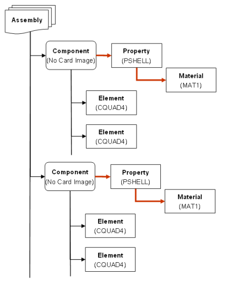
Figure 1. Solver Group 1. OptiStruct, Abaqus, Nastran
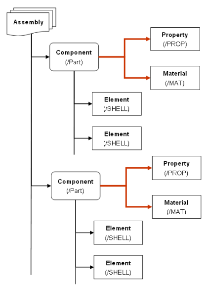
Figure 2. Solver Group 2. Radioss, ANSYS, LS-DYNA, PAM-CRASH, Permas
By Component Hierarchy
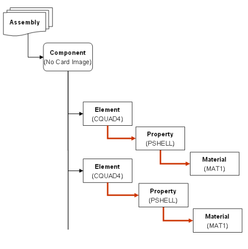
Figure 3. Solver Group 1. OptiStruct, Abaqus, Nastran
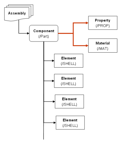
Figure 4. Solver Group 2. Radioss, ANSYS, LS-DYNA, PAM-CRASH, Permas
Duplicate Entity IDs
IDs that are duplicated within element and property groups for the LS-DYNA user profile are supported in HyperWorks Desktop.
For example, elements like beam and shell can now be imported without renumbering even if they have the same ID. Although it is not recommended to use duplicate IDs, this support has been implemented for greater flexibility for users who need to import models that already contain duplicate IDs. This support helps to preserve data integrity between HyperWorks Desktop and the solver by mimicking the solver's data rules. This support is provided by several means:
LS-DYNA data decks that have duplicated IDs are no longer automatically renumbered by HyperWorks Desktop. The ID numbers for elements and properties are preserved regardless of duplication. However, renumbering is still in effect for other entity types.
In an FE input, if the FE overwrite option is selected, IDs are overwritten only within the same ID group.
From the Preferences drop down menu, select the Meshing Options panel to see the allow duplicate IDs option. This can be selected to enable the duplication of IDs across pools of new elements or properties you create in HyperWorks Desktop. For example, ID 1 can be used for a shell element and a solid element. However, ID 1 cannot be used for two shell elements. By default, the option is not selected and HyperWorks Desktop never creates entities with the same ID during renumbering or meshing, and uses a sequential numbering scheme. With the exception of importing decks, the HyperWorks Desktop support of duplicate IDs must be manually activated.
When you attempt to select properties or elements for editing or deletion and you choose the by id option, you now must select an ID group, such as ELEMENT_SHELL or ELEMENT_BEAM, in addition to the ID, if the ID is present in more than one group. This selection is required to identify specific IDs if there is duplication across ID groups. For example, if both beam and shell have element ID 1, and you select an element by ID=1, a pop-up window appears that allows you to select between the two available groups that contain ID 1.
Import Session Files
Import session files into your current session.
-
Import a session file in the following ways:
- From the menu bar, select .
- From the Standard toolbar, click
 (Import
Session).
(Import
Session).
- In the Import Session File dialog, navigate to your working directory and open the session file (*.mwv).
Import Geometry
Import CAD files.
-
Import geometry in the following ways:
- From the menu bar, click .
- From the Standard toolbar, click
 (Import
Geometry).
(Import
Geometry).
The Import - Geometry tab opens. -
Click and select the
file(s) to import.
Remove files from the File Selection pane by clicking
(Remove
Selection) and (Remove
All). -
Define CAD import options by clicking to the left of
Import Options.
CAD Import Options
CAD readers provide options for processing data during import.
You can access some of these options from the Import browser, while other options are accessed from a reader's _reader.ini file.
Assembly
- Create multiple components for linear members
- Create multiple components for each member part.
- Create multiple components for stiffeners
- Create multiple components for each stiffener (one for each property; that is, if we have flange and web, then two different properties and components are created).
- Hierarchy as
- Type of hierarchy to generate.
- Choose Assemblies to generate an assemblies/components based hierarchy.
- Choose BOM Only to generate an empty part-based hierarchy.
- Choose Parts to generate a full part-based hierarchy.
- Insert name field
- Customizes the organization and names of components (NX parts). The naming
options are specified using the Format option.
- Choose <Part Name> to use the string attribute
DB_PART_NAMEfrom the part. If that attribute does not exist, the part file name is used. - Choose <Part Number> to use the string attribute
DB_PART_NUMBERorDB_PART_NOfrom the part. If that attribute does not exist, the part filename is used. - Choose <Category> to create and name components based off of the NX categories associated with the geometry.
- Choose <RID-PDI> to use the string attribute
DB_PART_REVfrom the part. - Choose <Layer> to create and name components based off of the layers of the geometry being imported.
- Choose <Instance Name> to use the name of the part's instance in an assembly. If the part is the root of an assembly, the part filename is used.
- Choose <Material Name> to use the name of the material if a material is specified for the geometry being imported. Otherwise, the name of the component is unaltered.
- Choose <Thickness> to use the thickness value if the geometry being imported is a midsurface with thickness information. Otherwise, the name of the component is unaltered.
- Choose <UG Body ID> to use the internal numerical ID of each geometric body. This value is unique for each geometric body imported.
- Choose <UG Tag> to use the internal numerical tag of the part instance. This value is unique for each part instance imported.
- Choose <Part Name> to use the string attribute
- Sample component name
- This corresponds to the NX Part Browser Assign components by name option; the default value is "default", that is the standard component naming. Name corresponds to the Insert name field option in < > (brackets).
- Single part only
- Consolidate the hierarchy into a single part.
- Split components by
- Strategy used to split components, which is dependent on the CAD format.
Options include one or more of the following (based on CAD format):
- Choose Body to generate a body-based component.
- Choose Layer to generate a layer-based component.
- Choose Part to generate a part-based component.
- Choose Category to split components by category.
- Choose Material to split components by material.
- Choose Thickness to split components based on component thickness.
- Choose Custom to enable sub-options.
Topology
- Cleanup tolerance
- Can be Automatic or Manual.
- Create solids
- Creates solid entities. If unchecked, reads surfaces but does not create solid entities.
- Ensure manifold geometry
- Extracts the manifold body from a Parasolid general body that is non-manifold and/or of mixed topological dimensionality. If unchecked, extracts Parasolid general bodies as defined.
- Extend surfaces
- The imported surfaces are extended to match neighbor surfaces.
- Faceplates as surfaces
- Import faceplates as surfaces if the surface description is present in the file, otherwise import as curves.
- Import type
- Create an object based on the structure of the file.
- Imprint stiffeners
- Stiffener lines are projected onto close surfaces and create corresponding topological modifications to these surfaces
- Merge edges
- Edges are merged together, when possible, during import as part of the cleanup phase.
- Perform connectivity
- Import the model and compute connectivity. The surfaces will be connected. If unchecked, import the model without computing connectivity. The surfaces will not be connected. This option speeds up import, but may not be suitable for any other purpose than visualization.
- Pillars as surfaces
- Import pillars as surfaces if the surface description is present in the file, otherwise import as curves.
- Prefer detailed
- When multiple representations of an object are available, import the most complex one.
- Scale factor
- Define the model scaling factor during import.
- Split periodic faces
- Split periodic surfaces to improve the quality and robustness of the import.
- Stiffeners as surfaces
- Import stiffeners as surfaces if the surface description is present in the file, otherwise import as curves.
- Stiffener/beam/ER systems as
- Can be one of the following:
- Solids - Imports these objects as solid entities.
- Landing curves - Imports these objects as just the landing curves.
- Landing curves and midsurfaces - Imports these objects as both landing curves and midsurfaces.
- Midsurfaces - Imports these objects as midsurfaces.
- Stitch across bodies
- Stitch surfaces belonging to different components.
- Stitch different sheets
- Stitching across different sheet bodies belonging to the same part/instance.
- Target Units
- Target unit system to be adopted for the imported model.
- Choose a specific unit.
- Choose CAD units to match the unit system to the CAD file being imported. If the target unit system does not match the CAD file being imported, than the corresponding numbers are modified to account for the unit change.
- Alternatively, choose Scale Factor to adopt the CAD unit system and scale the entities by the indicated factor.
- Tolerance value
- The reader considers this tolerance as the object space tolerance used to process the CAD data.
- Trim surfaces using
- Method for trimming surfaces. Can be:
- Parametric curves
- Model curves
- Preferred representation
- Visualization only
- Import the model for visualization purposes only. This skips many of the import steps (cleanup, stitching, solid creation, and so on) to provide a faster import. The resulting model may not be suitable for other uses.
Entities
- Assign properties to components
- Assign properties to the corresponding component (for components that have more than one property, properties are not assigned).
- BREP and tessellation
- Import B-rep or tessellation, with B-rep given preference. If B-rep is
present, tessellation is not imported (default). Choose from the
following:
- BREP or tessellation
- BREP and tessellation
- BREP only
- Tessellation only
- Compartments
- Import both compartments in the files, and compartments defined by “Faces.” The former by importing the geometry, the latter just by creating a metadata; also reference planes are created, because they can be referenced by compartments.
- Coordinate systems
- Import CAD coordinate systems as system collectors.
- Cutout profiles
- Import cutout profiles.
- Disable layers
- This corresponds to the NX Part browser Disable option in Layer filtering mode. The layers to disable in the import should be listed with the same rules as for the NX Part browser entry.
- Enable layers
- This corresponds to the NX Part browser Enable option in Layer filtering mode. The layers to enable in the import should be listed with the same rules as for the NX Part browser entry.
- FE models
- Import FE models.
- Filtering
- This corresponds to the NX Part browser Layer filtering selection.
- Free curves
- Import free curves (wireframe entities) into the model.
- Free points
- Import free points into the model.
- Groups as regions
- Create region entities corresponding to groups.
- Hidden (blanked/no show)
- Import entities that are hidden, blanked, or no show.
- Hidden ply surfaces
- Read hidden ply base surfaces.
- Holes
- Create holes.
- IGES compartments
- Import compartments in the files.
- Layer filter
- Import only the specified layer filters. The string should be in the form of
"
%filter1%filter2%filter3". The filter names are listed, separated by a character that you choose, and inserted as the first element of the string. The example uses '%' as a separator. You can choose another character as a separator, in case one of the listed attribute names contains '%'. HyperWorks Desktop will recognize it as it is the first character of the string. A special value ofDEFAULTcan be used to indicate the default layer filter. - Midsurfaces
- In batch mode, and when
@Display=layerfiltering, midsurfaces are imported. In GUI import when Creation type is set to Assemblies, this initializes the corresponding option in the NX Part browser. - Notch profiles
- Import notch profiles.
- Panel profiles
- Create curves along the panel profiles.
- Parameters prefix
- Only import parameters with this prefix. All others will not be imported.
- Plane size factor
- A factor > 0 for sizing of infinite planes. The factor is a percentage of the modal size.
- Ply contour gap tolerance
- Ply contour gap tolerance (default 0.3).
- Publications
- Create regions from the geometry referenced in publications.
- Selected categories
- This corresponds to the NX Part browser option Categories; they should be
listed as they are written in the command file string:
“<name1_length> <name1> <name2_length>
                            <name2>…”
, where<name<i>_length>is a number representing the string length of the ith category name. - Skip entities
- Specific entity types, or even subtypes (that is entity types with specific form numbers) that should be skipped during import.
- Solids
- In batch mode, when
@Display= layerfiltering, solids are imported. In GUI import when Creation type is set to Assemblies, this initializes the corresponding option in the NX Part browser. - Solver
- Select the appropriate solver.
- Topological properties
- Create reference planes and sketch contours, and attach metadata to the systems that own these properties.
- Trim ply surfaces
- Trim ply base surfaces during import.
- Unbounded curved plates
- Import curved plates lacking boundary descriptions.
Metadata
- Attributes
- Import all generic attributes (global and related to single entities) as metadata.
- Body ID
- Assign body identifier as metadata.
- Color
- Read color attributes of geometric entities as metadata with integer values.
- Density
- Read density value as metadata.
- Full name
- Generate the full CAD name, as retrieved from the CAD part, as metadata. This consists of assembly name/part name/feature name/entity name.
- Layer
- Read layer value as metadata.
- Legacy hierarchy
- Generate metadata with the original CAD hierarchy within the part.
- Original ID
- Import original CAD entity IDs as metadata.
- Plate system attributes
- Create physical properties assigned in the XML to plate systems and bracket children as metadata.
- PMI
- Read PMI data for points. New points are created and PMI attributes are attached as metadata.
- Prefix string
- The string is prefixed to all metadata names. No prefix is used by default.
- Stiffener normals
- Attach some metadata with information about normals to stiffener/beam/ER systems.
- Tags
- Create entity name as metadata.
- Unique ID
- Create metadata to track the unique CAD ID (default). The same identifier can be obtained for two entities when a single entity is split during import.
User Defined
- Options
- Use this GUI field to enter additional options not explicitly exposed in the
GUI, in the form
option1_name=option1_value,option2_name=option2_value, and so on. If an option also exposed in the GUI is mentioned in this field, the value of this field prevails. - Timeout (seconds)
-
Defines a timeout value (in seconds) that is used to abort the import of a CAD file. The timeout covers only the time spent in processing done within the third-party library calls (load and prepare the data to be sent to HyperMesh). Once the data is sent to HyperMesh the timeout no longer applies. This timeout applies individually to each CAD file being imported. If you import a single file (either an individual part or a master assembly file), it applies to the import of the entire file. If you import multiple files (such as selecting multiple files, or performing Representation Load from the Part Browser), it applies individually to each file.
Colors
- Colors
- Read color attributes of geometric entities as metadata with integer values in RGB format.
PDM Attributes
- Material name
- Name of the CAD attribute containing the PDM material name info of the current part. Default is MATERIAL_NAME.
- Mesh flag
- Name of the CAD attribute containing the PDM mesh flag name info of the current part. Default is MeshFlag.
- MID
- Name of the CAD attribute containing the PDM material ID info of the current part. Default is MaterialID.
- Part number
- Name of the CAD attribute containing the PDM part number info of the current part. Default is PartNumber.
- PID
- Name of the CAD attribute containing PDM property ID info of the current part. Default is PID.
- Revision
- Name of the CAD attribute containing PDM major revision info of the current part. Default is Revision.
- Thickness name
- Name of the CAD attribute containing the PDM thickness info of the current part. Default is Thickness.
- UID
- Name of the CAD attribute containing the PDM UID info of the current part. Default is UID.
Default versions of the _reader.ini files are included in the directory [Altair Home]/io/afc_translators/bin/[platform] directory and its children. When a CAD reader is activated, each reader first checks the current working directory for the appropriate _reader.ini file. If the file is not found, the translators looks in all directories pointed by the HW_CONFIG_PATH environment variable.
As a last resort, the translator uses the default _reader.ini file in the above directory. In this way the _reader.ini file can have "global" or "local" user scope. For instance, "local" user changes for a current job can be made by copying and modifying the _reader.ini file in the local current working directory.
Options can take on only one value at a time. Options can also be commented out (ignored) by placing a # in front of an option, in which case the default value for that option will be used.
Many CAD translators also import other relevant information as metadata attached to specific entities (assemblies, components, points, lines, surfaces, solids). Some metadata is generated by default while other metadata is generated by enabling/disabling certain options in the _reader.ini files. Metadata is stored in the database and can be used for review or to perform process automation. For example, you can obtain the tag (name) of a surface from the CAD file and apply certain mesh criteria to that surface inside HyperWorks Desktop.
Import BOMs
Import bill of material files.
-
Import BOMs in the following ways:
- From the menu bar, select .
- From the Standard toolbar, click
 (Import BOMs).
The Import - BOM tab opens. -
Define BOM import options by clicking to the left of Import
Options.
Import Connectors
Import connector files.
-
Import Connectors in the following ways:
- From the menu bar, select .
- From the Standard toolbar, click
 (Import
Connectors).
(Import
Connectors).
The Import - Connector tab opens. -
Define import options by clicking to the left of Import
Options.
- 0D: Spotweld, bolt, screw, gumdrop, clinch, rivet (blind, self-piercing, solid, swop), robscan, contact_list, threaded connection, heat stake, clip, nail
- 1D: Sequence connection 0D (spotweld, gumdrop), seamweld (butt_joint, corner weld, edge weld, i_weld, overlap weld, y-joint, k-joint, cruciform joint, flared joint), adhesive-line, hemming, contact list
- 2D: Adhesive face
- Custom attributes are managed.
- Appdata is not managed.
Import Markers
Import marker files into MediaView.
-
Import markers in the following ways:
- From the menu bar, select .
- From the Standard toolbar, click
 (Import Markers).
- In the Import Marker File dialog, navigate to your working directory and select the marker file to import.
Import Table CSV
Import a comma separated value file.
TableView supports multiple lines of data in a single cell. To add a line break, press Alt + Enter. In TableView, the Conditional Formatting and the Cell Data panels are disabled if you select a cell that contains multiple lines or if you press Alt + Enter.
-
Import CSV file in the following ways:
- From the menu bar, select .
- From the Standard toolbar, click
 (Import Table CSV).
- In the Import CSV File dialog, navigate to your working directory and select the comma separated value file to import.