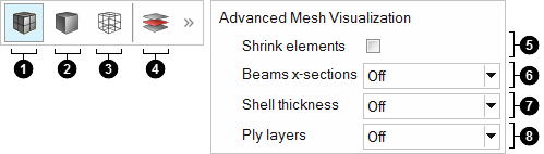
Shrink elements. Scale elements to the Shrink Factor specified
in the Appearance preferences.
Beams x-sections. Select a display setting for 1D beam
elements.
Off. Show a simple representation of 1D beam elements.
On. Show a more detailed, shaped-based representation for
1D beam elements.
Hybrid. Show both the simple and detailed representations
for 1D beam elements.
Shell thickness. Select a display setting for 2D shell
elements.
Off. Show a simple representation for 2D shell
elements.
On. Show a more detailed, shaped-based representation for
2D shell elements.
Hybrid. Show both the simple and detailed representations
for 2D shell elements.
Ply layers. Select a display setting for ply layers.
Off. Hide ply layers.
On. Show ply layers.
On + fiber direction. Show ply layers with vectors to
indicate the appropriate ply orientation. Corrected fiber directions display if the
drape data is available on every element of the ply.
Edges only. Show the ply lay-up or stack boundaries, which
provides an easy way to view ply drop-off. When the stack topology shape is changed,
the visualization of the edges is automatically updated. Ply layer geometry edges
are always outlined in white, where as FE edges are always outlined in the same
color as the ply. FE edges are always outlined with a thicker line compared to
geometry edges.
 and select a mesh display option.