Graphical Selection
Select and deselect entities to modify with other HyperLife Weld Certification tools. Selected entities are outlined to indicate their selection state.
Hover over an entity to highlight it.
In idle mode, entities can be selected from either the modeling window or the browser area. Selecting an entity in the modeling window automatically selects the corresponding entity in the browser and vice versa.
When working in a tool, entities should be selected from the modeling window.
Entity Selectors
Use entity selectors to specify which type of entity you are able to select.
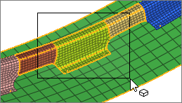
Entity selectors act as a filter by limiting your selection to a single entity type in the modeling window. For example, if an entity selector is set to Surfaces, only surface are available for selection. If it is set to Points, you can draw a window around the entire model and only the points will be selected. After performing a selection, the number of selected entities appears in parenthesis.

Figure 1.
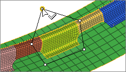
If a selector supports multiple entity types, click the arrow to view a drop-down menu of available options.
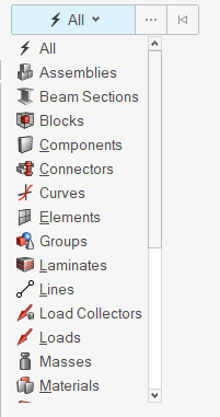
Figure 2.
Entity selectors do not affect your selection in a browser. The entity selector in the modeling window will automatically update to match the selected entity type. You're also able to select multiple entities of different types in a browser.
When working in a panel, the above selectors are disabled and the yellow panel selectors take precedence.
- Use keyboard shortcuts to change the active entity type in an entity selector.
- In idle mode, convert your selection to a new entity type by changing the entity selector. For example, if you select elements, and then set the entity selector to nodes, all of the nodes associated with the selected elements will be selected.
Select Single Entities
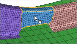
Figure 3.
Append and Remove Entities From a Selection
-
In the modeling window:
- Append entities to your selection by holding Ctrl while left-clicking.
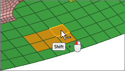
- Remove entities from your selection by holding Shift while left-clicking.
Figure 4.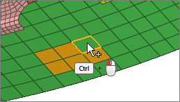
-
Clear your selection in the following ways:
- Left-click in empty space.Note: Only available in idle mode.
- Click
 on an active entity selector.
 - Press Backspace to clear the active entity selector.
- Press Esc to clear all entity selectors.
- Left-click in empty space.
Select Multiple Entities Simultaneously
- For box, circle, or freehand selection, click-and-drag to draw a selection window.
- For polyline selection, click-and-drag to draw a line, then release the mouse to create an end point. Continue drawing lines, then left-click the start point, middle-mouse-click, or press Enter to close the selection window.
 |
 |
Window Selection Settings
Change window selection settings from the modeling window right-click context menu.
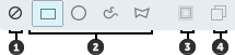
Figure 6.
- Window Select Disabled. Disable window selection. Allows for fast clicking without the risk of dragging a mini window.
- Window Shape. Change the shape of the selection window when you drag your mouse.
- Intersection. Select entities that intersect the window. Available for elements, lines, and surfaces.
- Only Select Visible. Only select visible entities. Available for elements.
Perform Extended Entity Selection
Use extended entity selection to find, filter, and select subsets of entities. You can also save and retrieve previous selections.
-
Use the Advanced Selection dialog, which can be opened in
the following ways:
- Click
 next to an entity selector.
 - Press Spacebar.
- Right-click in the modeling window and choose .
Pick a selection method from the drop-down menu in the top-left of the dialog then select a subset of entities.The process for selecting entities varies depending on the method.
Tip: The options in the context menu beneath Advanced (By Entity, By ID, etc. ) correlate to different selection methods in the Advanced Selection dialog. Choosing one of these options opens the dialog with the selected method. - Click
Extended Entity Selection Options
The following options are available for extended entity selection.
Context Menu Options
- Displayed
- Select all entities of the specified type currently displayed in the modeling window.
- Reverse
- Allows for a Boolean "not" to be performed on the currently displayed entities; all selected entities are removed from the mark; all entities which are not on the mark and are currently active are selected.
- All
- Select all entities of the specified type. The set to be added to the user mark includes entities displayed and those not displayed.
- Adjacent
- Select entities adjacent to the entities already selected.
- Attached
- Select entities by specifying an entity among a large group of continuously connected elements. HyperLife Weld Certification includes the entities currently displayed that are attached to the entities already selected. Entities that are not displayed will not be selected although they may be attached to the entity selected.
- Face
- Select entities by surface face. HyperLife Weld Certification finds entities that are attached to each other without crossing a feature line. The Geometry feature angle option in determines the feature lines. Attached, adjacent surfaces or elements are progressively selected when the angle between them is less than or equal to the specified feature angle.
- Similar
- Select entities that are similar to the your current selection based on config.
- Save Selection
- Save the currently selected entities to a holding area known as the user mark.
- Retrieve Selection
- Retrieve previously saved entities from the user mark.
Advanced Selection Dialog Options
- By Assembly
- Select entities by assembly.
- By Block
- Select entities associated with one or more block entities.
- By Collector
- Select elements, lines, surfaces, loads, coordinate systems, vectors, equations, and points by collector.
- By Component
- Select entities by component.
- By Config
- Select elements by configuration and type. The element type is dependent on the template file.
- By Connector Group
- Select entities associated with one or more connector groups.
- By Domains
- Select entities associated with a morph domain.
- By Edge
- Select entities (nodes, elements) by surface edge. HyperLife Weld Certification finds entities that are attached to each other without crossing a feature line. The feature line can be adjusted using the Angle slider. Attached, adjacent surfaces or elements are progressively selected when the angle between them is less than or equal to the specified feature angle.
- Click
 to
view more options.
to
view more options. - By Face
- Select entities (nodes, elements) by surface face. HyperLife Weld Certification finds entities that are attached to each other without crossing a feature line. The feature line can be adjusted using the Angle slider. Attached, adjacent surfaces or elements are progressively selected when the angle between them is less than or equal to the specified feature angle.
- Click to
view more options.
- By Group
- Select entities by group.
- By Handles
- Select entities associated with morphing handles.
- By ID
- Select entities by typing in their ID numbers.
- By Include
- Select FE entities such as elements, loads, and groups that belong to the selected include.
- By Laminate
- Select entities associated with one or more laminate entities.
- By Line
- Pick lines in the modeling window. Entities associates with the lines are selected.
- By List
- Select entities from a list.
- By Material
- Select entities by material.
- By Morphing Volumes
- Select entities associated with morphing volumes.
- By Multibodies
- Select entities associated with one or more multibody entities.
- By Output Block
- Select the nodes, elements, comps, systs, groups and mats within an outputblock.
- By Part
- Select entities associated with a part.
- By Path
- Pick multiple nodes, lines, or elements and select all the nodes/lines/elements that fall in the closest connecting path. If you select two nodes on a free edge of some elements, the function tries to find the closest path along that free edge. This function uses the connectivity of the elements between the nodes, and thus requires the selected nodes to be part of a continuous shell mesh. Similarly, By Path for lines uses the connectivity of surfaces/solids and thus requires the selected lines to be surface/solid edges.
- By Ply
- Select entities associated with one or more ply entities.
- By Points
- Pick points in the modeling window. Entities associates with the points are selected.
- By Property
- Select entities by property.
- By Set
- Select the entities within a set.
- By Solid
- Pick solids in the modeling window. Entities associates with the solids are selected.
- By Surface
- Pick surfaces in the modeling window. Entities associates with the surfaces are selected.
- By Width
- Select surfaces by width, either by picking a sample surface or by specifying a range of values for the width.
Keyboard Shortcuts & Mouse Controls
Selection
| To do this | Press |
|---|---|
| Window select | Left Mouse Drag |
| Append selection | Ctrl + Left Mouse Click |
| Deselect | Shift + Left Mouse Click |
| Select displayed | Ctrl + A |
| Select all | Ctrl + Shift + A |
| Select adjacent | Ctrl + J |
| Select similar (based on type and config if applicable) | Ctrl + M |
| Reverse selection | Ctrl + R |
| Open advanced selection | Spacebar |
| Select elements By Face or By Edge | Alt + Left Mouse Click |
| Adjust feature angle when selecting elements By Face or By Edge | Alt + Scroll |
| Select nodes and lines By Path | Alt + Left Mouse Click |
| Edit | Double Mouse Click |
| Suspend snaps | Alt |
| Clear active selector | Backspace |
| Clear all guide bar selectors | Esc |
Entity Selector
| To do this | Press |
|---|---|
| Set to components/connectors | C |
| Set to elements | E |
| Set to laminates/lines/loads | L |
| Set to materials | M |
| Set to nodes | N |
| Set to plies/points/properties | P |
| Set to solids/surfaces/systems | S |
| Set to all | Esc + Esc |
Select Entities From a Panel
When working in a panel, selection is performed via yellow entity selectors.
The yellow entity selectors allow you to indicate which entities are to be modified when a function is performed in a panel. Their behavior is similar to the entity selectors elsewhere in the application.

Figure 7. Entity Selector
To change the data type, click the entity selector switch to access the pop-up menu of possible data types and select the type you want to use.
In addition to selecting one entity at a time on the screen, you can select multiple entities via quick window selection.
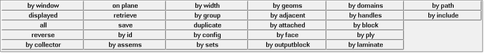
Figure 8. Extended Entity Selection Window
These selection options display for all of the entity types supported in the active client. Selections that are not valid for the current entity type are grayed out.
If you want to reset the entity selections, click the reset button to deselect all selected entities.
If the data type is a line list, click the data type of the entity selector to see the selected entities in the order in which they were selected.
- by list
- Allows you to pick the nodes individually from the node list.
- by path
- Allows you to select a few nodes that form a path, which will be used to automatically select all the displayed nodes that lie in the shortest path of the nodes selected. If you select nodes on the edges of a part, the function tries to find the closest path along the edges of that part. By path follows the connectivity of the elements between the nodes selected. Therefore, if the nodes selected are not connected by elements, this function does not apply.
- show node order
- Allows you to view the nodes currently stored in the nodelist collector by numbering the nodes in the sequence of their selection.
- by window
- Allows you to select nodes by window and internally the order of the nodes selected is determined based on its spatial location and element connectivity (if connecting elements exist).
- by list
- Allows you to select lines or surface edges individually in the desired sequence.
- by path
- Allows you to pick surface edges (two or more) and selects all the surface edges that fall in the closest path connecting the selected edges. If you select two free (red) edges, the function tries to find the closest path along the free surface edges. Since this function uses the connectivity of the surfaces, it only works with surface edges and not with free unconnected geometric lines.
Extended Entity Selection Menu
The extended entity selection menu provides a number of entity selection options.
Figure 9. Entity Selector
Figure 10. Extended Entity Selection Menu
- By right-clicking in the modeling window.
- In the Advanced Selection dialog by clicking on an entity selector.
| Option | Description |
|---|---|
| by window | Select entities inside a user-defined multiple-sided polygon in the plane of the screen. Selecting by window activates the Build Window panel. Select points in the graphics area to define a window enclosing the pick handles of the desired entities. Click select entities to highlight the enclosed entities. Alternatively, click reject entities to deselect enclosed entities that were previously highlighted. |
| displayed | Select all of the entities currently displayed on the screen. When disp is selected, all entities within collectors that are active in the disp (display) panel are selected. |
| all | Select all entities of the specified type. When you select all, the set to be added to the user mark includes entities displayed and those not displayed. |
| reverse | Allows for a Boolean "not" to be performed on the currently displayed elements. When reverse is selected, all selected elements are removed from the mark; all elements which are not on the mark and are currently active are selected. |
| by collector | Select elements, lines, surfaces, loads, coordinate systems,
vectors, equations, and points by collector. When you select by
collector, HyperLife Weld Certification displays a list of the
available collectors. You may select multiple collectors from
this list. If you select component collectors in regard to elements or lines, the elements or lines contained in the selected components are selected. With all other entities, the entities selected by this operation are those attached to the selected component. |
| on plane | Select a group of entities whose pick handles reside on a plane. This is useful when you want to apply constraints to a plane. |
| retrieve | Retrieve previously saved entities from the user mark. Entities can be saved to the user mark by selecting save in this pop-up window, or by selecting save failed in the Check Elems panel. |
| save | Save the currently selected entities to a holding area known as the user mark. |
| by id | Select entities by typing in their ID numbers. When you
select by id, a pop-up window prompts you
to type ID numbers or ranges of ID numbers. You can use
keywords to specify a range that determines which entities
are selected. The standard format is: Examples of valid by id expressions:
You can also use a comma to separate individual entities or entity ranges. Examples of valid lists of
by id expressions:
|
| by assems | Select entities by assembly. When you select by assems, HyperLife Weld Certification displays a list of the available assemblies. You may select multiple assemblies from this list. |
| by width | Select surfaces by width, either by picking a sample surface or by specifying a range of values for the width. |
| by group | Select entities by group. When you select by group, HyperLife Weld Certification displays a list of the available groups. You may select multiple groups from this list. |
| duplicate | Duplicate the currently selected elements, lines, surfaces, or points. When you select duplicate, a pop-up window allows you to choose a component for the newly created duplicate entities. Select current to place the new entities in the currently active component collector. Select original to place the new entities in the same component collectors as the original entities. The initially selected entities are deselected when the duplicate elements are created and selected. This can be very useful when you use the reflect function on a model (only available for elements and lines). |
| by config | Select elements by configuration and type. When you select by config, HyperLife Weld Certification displays a panel for specifying an element configuration and type for selection. The element type is dependent on the template file. |
| by sets | Select the entities within a set. When you select by sets, HyperLife Weld Certification displays a list of the available sets from which you may select. Sets are created in the Entity Sets panel. |
| by geoms | Select the entities which are associated to a surface or solid. When you select by geoms, HyperLife Weld Certification displays a panel from which you may select one or more surfaces or solids. Once the geometric entities have been picked, click add to selection or subtract from selection. HyperLife Weld Certification selects the entities which are associated to the selected geometry. You can associate entities to a surface in the Node Edit panel. |
| by adjacent | Select entities adjacent to the entities already selected. When you select by adjacent, HyperLife Weld Certification includes the entities that are adjacent to the entities already selected. |
| by attached | Select entities by specifying an entity among a large group of continuously connected elements. When you select by attached, HyperLife Weld Certification includes the entities currently displayed that are attached to the entities already selected. Entities that are not displayed will not be selected although they may be attached to the entity selected. |
| by face | Select entities (nodes, elements) by surface face. It finds entities that are attached to each other without crossing a feature line. The feature angle parameter in the Options panel’s mesh and geometry subpanels determine the feature lines. Attached, adjacent surfaces or elements are progressively selected when the angle between them is less than or equal to the specified feature angle. |
| by output block | Select the nodes, elements, comps, systs, groups and mats within an outputblock. When you select by output block, HyperLife Weld Certification displays a list of the available output blocks from which you may select. Output blocks are created in the Output Blocks panel. |
| by domains | Select entities associated with a morph domain. When you select by domains, HyperLife Weld Certification displays a new panel in which you can pick and select the desired domains. |
| by handles | Select entities associated with morphing handles. When you select by handles, HyperLife Weld Certification displays a new panel in which you can pick and select the desired handles. |
| by block | Select entities associated with one or more block entities. When you select by block, HyperMesh displays a new panel in which you can pick and select the desired blocks. |
| by ply | Select entities associated with one or more ply entities. When you select by ply, HyperLife Weld Certification displays a new panel in which you can pick and select the desired plies. |
| by laminate | Select entities associated with one or more laminate entities. When you select by laminate, HyperLife Weld Certification displays a new panel in which you can pick and select the desired laminates. |
| by path | Pick multiple nodes or lines, and selects all the nodes/lines that fall in the closest path connecting the selected ones. If you select two nodes on a free edge of some elements, the function tries to find the closest path along that free edge. This function uses the connectivity of the elements between the nodes, and thus requires the selected nodes to be part of a continuous shell mesh. Similarly, by path for lines uses the connectivity of surfaces/solids and thus requires the selected lines to be surface/solid edges. |
| by include | Select FE entities such as elements, loads and groups that belong to selected include. When you select by include, HyperLife Weld Certification displays a list of the available includes that you may select. |
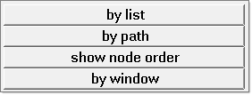
Figure 11.
| Option | Description |
|---|---|
| by list | Select nodes individually in the desired sequence. |
| by path | Pick nodes (two or more) and selects all the nodes that fall in the closest path connecting the selected nodes. If you select two nodes on the free edge of the elements, the function tries to find the closest path along the free edge. This function uses the connectivity of the elements between the nodes and thus requires the selected nodes to be part of a continuous shell mesh. |
| show node order | Review the nodes currently stored in the nodelist collector by numbering the nodes in the sequence of their selection. |
| by window | Select nodes by window and internally, the order of the nodes selected is determined based on its spatial location and element connectivity (if connecting elements exist). |
| Option | Description |
|---|---|
| by list | Select lines or surface edges individually in the desired sequence. |
| by path | Pick surface edges (two or more) and selects all the surface edges that fall in the closest path connecting the selected edges. If you select two free (red) edges, the function tries to find the closest path along the free surface edges. Since this function uses the connectivity of the surfaces, it only works with surface edges and not free unconnected geometric lines. |
Card Filter
Use the Card Filter to restrict the list of entities displayed when you click the entity selector.
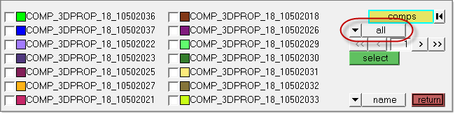
Figure 12. Card Filter. Card Filter is outlined in red.
Some panels present a list of entities when you click their Entity Selector button instead of the Extended Entity Selection options.
| Assembly | Beamsection collector | Blocks |
| Component | Contact surfaces | Control volume |
| Curves | Ddvals | Groups |
| Laminates | Load collector | Load steps |
| Material | Multibodies | Plies |
| Plots | Property | Sensors |
| Sets | Shapes | System collector |
| Tags | Titles | Vector collector |

Figure 13.
This displays a read-only text field adjacent to the Card Filter control. Click card to open a pop-up window that lists all of the cards defined in your model for the selected type of entity, and pick the card that you wish to filter by.
Once selected, only entities with the chosen card type will display in the entity list on the panel.
To remove the filter, simply use the switch to select all, displaying all entities regardless of card association, or no card, displaying only those entities that do not have a card at all.
Select Nodes on Geometry or Elements
Node and node list entity selectors allow you to not only select existing nodes in the model, they also allow you to create new nodes on geometry or on elements.
You can create a node on geometry by holding the left mouse button down along the geometry handle until the cursor becomes a square and then selecting the geometry (lines, edges, surfaces) on which you would like to place a node. Then, move your cursor to the exact location on the geometry where you would like the node to be placed and click the left mouse button to place a node. You can create nodes on elements by holding the left mouse button down on an element handle until the cursor becomes a square and selecting the element. Then, move the cursor to the exact location on the elements of that component and click the left mouse button to place the node.
-
Select new nodes on geometry.
-
Position the cursor on a node and press the left mouse button.
The cursor becomes a small white box
 .
.
-
Position the cursor on a node and press the left mouse button.
-
Select new nodes on elements.
Select Entities in the Modeling Window
After you select the correct data type, you can use the mouse to select the desired entities in the modeling window.
The graphics engine allows you to select entities by moving the mouse anywhere along the entity of interest. For lines and surfaces, it is much easier to work when you are zoomed in on a particular area, as you are not required to have a pick handle on the screen in order to pick the entity.
Another key feature in the graphics engine is the method by which nodes are selected. To select a node, select the element to which the node of interest is attached. HyperLife Weld Certification selects the node closest to the point where the element was selected. The benefit of this feature is that it allows you to create zero length elements between two coincident nodes in a mesh.
For nodes that are not attached to any elements, HyperLife Weld Certification allows you to select the node by picking the "node sphere" on the screen.
Each type of entity has a pick handle that allows you to select the entity.
| Entity | Pick Handle | ||
|---|---|---|---|
| Nodes | The pick handle for a node is located at the node. To select a node, move the mouse to the location on the screen where the node resides. If you need to select nodes on geometry or on an element where nodes do not currently exist. | ||
| Elements | Shell and solid element pick handles are displayed as
pixels at the centroid of the element. 1D element pick
handles are displayed as letters at the centroid of the
elements:
Element handles can be selected whether or not they are displayed. |
||
| Lines | Each segment of a line has pick handles along its length. Each pick handle is displayed as a small "+." If there are many pick handles, a "+" is displayed at only some of the pick handles. | ||
| Surfaces | Surfaces do not have pick handles. Surfaces can be selected along their edges or on interior UV lines, also known as surface lines. | ||
| Components | Components do not have pick handles. A component can be selected by picking an element, line, or surface within that component. | ||
| Systems | The pick handle for a coordinate system is located at the origin of the system. | ||
| System Collectors | System collectors do not have pick handles. To select a system collector, simply select a system within that system collector. | ||
| Loads | The pick handle for a load is located at the pick handle of the entity to which the load is applied. | ||
| Load Collectors | Load collectors do not have pick handles. To select a load collector, simply select a load within that system collector. | ||
| Plots | A plot can be selected by picking within its border. | ||
| Blocks | Blocks do not have pick handles. Blocks are drawn in shaded mode with transparency and can be selected by picking anywhere on the entity. | ||
| Titles | A title can be selected by picking within its bounding box. | ||
| Vectors | Vector pick handles are located at the arrow tip of the vector. | ||
| Curves | A curve can be selected by clicking anywhere along the curve. |
User Features of the Graphics Engine
When you are post-processing, the graphics engine offers advanced and powerful features.
- Cutting plane
- Cutting plane functions have been expanded to allow three planes to be active simultaneously. Cutting plane control is more interactive and is controlled by selecting any of the active planes with the mouse and then dragging the plane across the model. The cutting plane feature can be found in the Hidden Line, Contour, and Animation panels.
- Isosurfaces
- The isosurfaces subpanel is available on the Contour and Animation panels. Isosurfaces can be displayed on a model in either a legend-based mode in which each of the legend colors generates an isosurface, or as a value-based surface in which you specify a value that indicates where an isosurface should be displayed.
- Hidden components
- If one or more of the components in a model are set to a display style besides wireframe, then HyperLife Weld Certification draws the whole model in hidden line. To perform this task, HyperLife Weld Certification relies on the z-buffer found on your graphics device. The z-buffer allows HyperLife Weld Certification to render your model in hidden line, with the elements in back eliminated from the display. There are some limitations to using a z-buffer and some display output differences of which you should be aware.
- Optimization
- The graphics engine optimizes the display of your finite element model. One of the optimizations is the removal of interior solid faces. If you have solid elements in your model, HyperLife Weld Certification calculates where the external faces are in your model, and displays these instead of displaying all of the faces.
- Memory usage
- HyperLife Weld Certification graphics use some memory. If swapping occurs while you are running HyperLife Weld Certification, this could seriously affect performance. If you encounter this problem, you should obtain more system memory.