Create elements
All element types can be created.
| 1. | From the Menu Bar, select Mesh Editing > Element > Create. |
or
If the Mesh Editing panel is already open, select Element > Create from the pull-down menu in the panel.
| 2. | Enter a name in the Part creation field and click Ok to create a new part. (All the created elements will be added onto this new part.) |
or
| • | Click  and pick a part in the graphic window. and pick a part in the graphic window. |
| • | Click  to add parts by box selection and answer the question in the Dialog menu bar with Yes or Cancel. to add parts by box selection and answer the question in the Dialog menu bar with Yes or Cancel. |
The default box is rectangular. Use the SHIFT key to define a polygon box.
| • | Click  to select a part (only one) in the tree. (All the created elements will be added onto this selected part). to select a part (only one) in the tree. (All the created elements will be added onto this selected part). |
| 3. | Choose your element creation type: |
| • | Switch the toggle button Elements / Meshing OFF to mesh a plane with four-nodes shell elements by selection for the edge. |
| • | Switch the toggle button Elements / Meshing ON to create any type of element one-by-one. |
Element type selection Meshing
| 1. | The Property File window appears. In the property database, select a shell property and validate with OK. |
| 2. | The Shell Property Card window appears. The parameters can be modified. |
| • | Click OK to save the property. |
| • | Click Cancel to cancel the property selection. |
| • | The Property File window appears. In the property database, select a shell property and validate with OK. |
| 3. | The Material File window appears. In the material database, select a shell material and validate with OK. |
| 4. | The Shell Material Card window appears. The parameters can be modified. |
| • | Click OK to save the material. |
| • | Click Cancel to cancel the material selection. |
| 5. | Switch OFF or ON the toggle button, Pitch / Number of nodes. |
| • | If the toggle button is ON: |
| - | Enter the mesh size (pitch) between Node 1 and Node 2. |
| - | Enter the mesh size (pitch) between Node 2 and Node 3. |
| • | If the toggle button is OFF: |
| - | Enter the number of nodes between Node 1 and Node 2. |
| - | Enter the number of nodes between Node 2 and Node 3. |
| 6. | Click  and pick four nodes on the graphic window with the same order as the shell element creation. and pick four nodes on the graphic window with the same order as the shell element creation. |
| 7. | Click  to view the mesh creation proposal. to view the mesh creation proposal. |
| 8. | Click Save to save the created elements; or |
Click Cancel to cancel the element(s) creation.
| 9. | Click Close to close the menu. |
Element type selection Element
| 1. | Click Choose an element type and select an element type from the list. |
A Property File window opens.
| 2. | In the property database, select a shell property and validate with OK. |
| 3. | The Shell Property Card window appears. The parameters can be modified: |
| • | Click OK to save the property. |
| • | Click Cancel to cancel the property selection. |
| 4. | The Property File window appears. In the property database, select a shell property and validate with OK. |
| 5. | The Material File window appears. In the material database, select a shell material and validate with OK. |
| 6. | The Shell Material Card window appears. The parameters can be modified. |
| • | Click OK to save the material. |
| • | Click Cancel to cancel the material selection. |
| 7. | Pick nodes in the graphic window to create the element: |
| • | two or three nodes for a spring element |
| • | four nodes for a four-nodes shell element |
| • | three nodes for a three-nodes shell element |
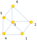
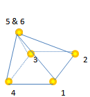
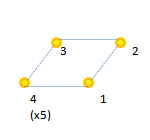
| • | eight nodes for the solid element: |
| o | eight different nodes for a hexahedron |
| o | six different nodes for a pentahedron, plus pick the fifth and sixth nodes a second time each to define nodes that collapse into the penta's fifth node. |
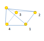
| o | four different nodes for a pentahedron's base, plus pick the fourth node four additional times. An automatic projection (in accordance with the predefined element quality criteria) from the fourth node creates a fifth node. |
| 8. | Select new nodes to create other elements in the same part. |
| 9. | When finished, click Cancel in the Dialog menu bar to stop the node selection. |
| 10. | Click Save to save the created elements; or |
Click Cancel to cancel the element(s) creation.
| 11. | Click Close to close the menu. |
See also
1D Element
2D Element
3D Element
Convert Element