HyperBeam Sections
Types of HyperBeam sections that can be defined.
- Standard Section
-
- Use Standard sections to define solver supported sections. Each supported solver has a library of supported sections, and section type and dimensions can be edited in HyperBeam.
- 3D visualization is available in Engineering Solutions.
- Shell Section
-
- Use Shell sections to define thin cross-sections with geometric lines or 1D elements. To create shell sections, use the shell and solid creation and editing tools or bring in geometry and element data from Engineering Solutions.
- When you create a shell beam section by cutting a cross-section through a shell mesh, any thickness that was assigned directly to the elements will be given to the shell section. The thickness applied to the section is equal to the average thickness for all elements in the component with each element getting equal weight. The number of elements matters, but the area of the elements does not. For composites, the thickness will be extracted treating the composites as homogenous.
- 3D visualization is available in Engineering Solutions.
- Solid Section
-
- Use Solid sections allow to define solid beam cross-sections with continuous 2D elements, connecting lines that have a closed loop, and continuous surfaces. To create solid sections, use the shell and solid creation and editing tools or bring in geometry and element data from Engineering Solutions.
- 3D visualization is available in Engineering Solutions.
- Generic Section
-
- Use Generic sections to define sections without defining actual cross-section geometry. Areas, inertias, centroids, and other coefficients are supported.
- No 3D visualization is available in Engineering Solutions.
- HyperBeam Sections
- Supported by the Samcef interface for the
creation of different beam sections. You can create the following beam
sections:
- Circle
- Circle 0
- H
- I
- L
- L2
- RECT
- RECT 0
- T
- U
- ZD
- ZD2
Example: Create Shell and Solid Sections Using the HyperBeam Sketcher
-
In the Model Browser, click
 to activate the HyperBeam view.
-
Once the defaults are set, the canvas will appear and you can start creating
parts with the shell part / solid perimeter tool (
 ).
Once clicked, the button remains highlighted until you move the mouse off of the canvas.
).
Once clicked, the button remains highlighted until you move the mouse off of the canvas.- Left-click to create a new vertex.
- Right-click to remove vertices in the reverse order they were created.
- Once the part is complete, move the mouse off of the canvas to finalize it.
Note: Each part has only one thickness, and it is common to have a section with multiple connecting parts.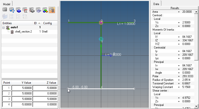
Figure 1. -
Use the Move vertex / Adjust Dimension tool (
 ) to click and drag vertices to snap points for shell
and solid sections, or to adjust parameters such as shell thicknesses or
standard section parameters.
) to click and drag vertices to snap points for shell
and solid sections, or to adjust parameters such as shell thicknesses or
standard section parameters.
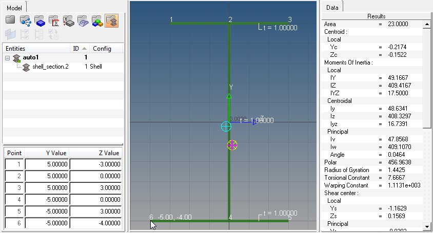
Figure 2. -
After the parts are created and assembled it is sometimes necessary to revise
the connectivity or change the part thicknesses.
This can be done in the part editor shown below. Each part is listed with its part name, thickness and connectivity, and as each part is selected it will highlight yellow on the canvas.
The connectivity order is simply the order in which the vertices are drawn for a given part. Remember to leave a space between each vertex when editing the connectivity order.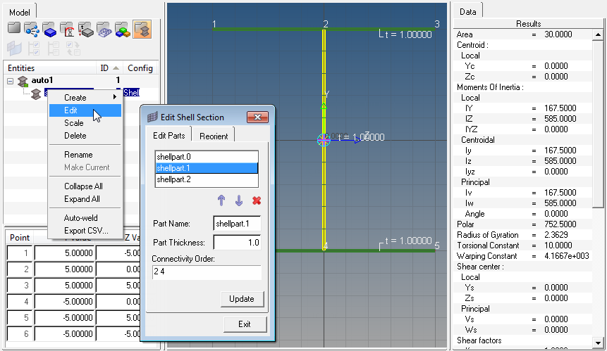
Figure 3. -
Redefine the local axis location and angle using the Reorient tab in the
Edit shell section dialog.
This becomes useful when comparing HyperBeam shell section properties (results) to more rigidly-defined sections. Note that changing the local axis in HyperBeam is not the same as using element offsets in a finite element model.
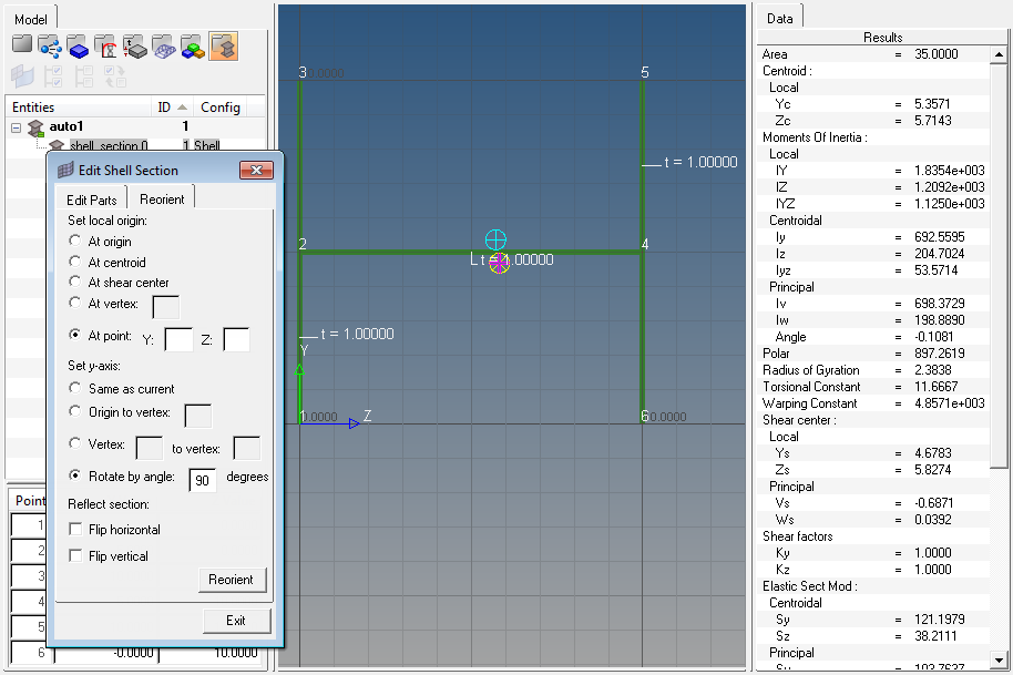
Figure 4.
The same toolset can be applied to sketching solid sections as well. You can start by right-clicking in the browser on the left-hand side, creating a new solid section, and defining defaults for Canvas, Grid and Snap sizes.
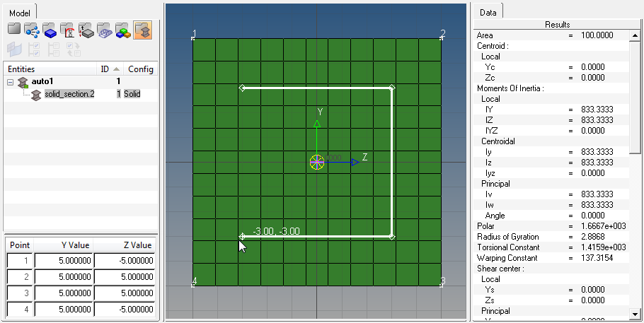
Figure 5.
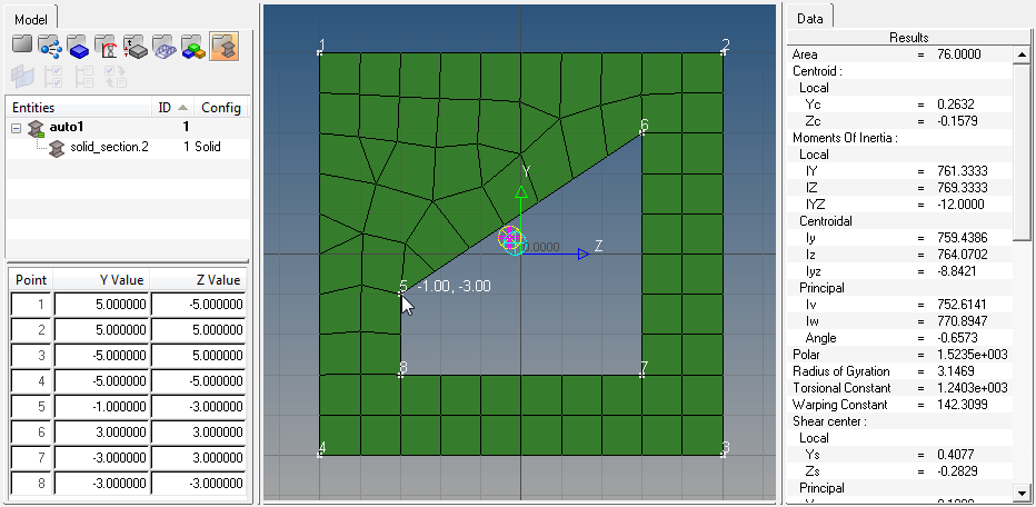
Figure 6.
As before, the Move vertex / Adjust dimension tool can be used to move vertices of solid sections. Each vertex movement requires a re-mesh of the solid section, so take care when moving vertices of complicated parts.
Example: Create and Assign a Standard Section
Create and assign a standard section to an OptiStruct PBARL property.
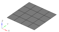
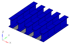
Figure 7. . The grey elements in the image to the left represent a structure that needs to be stiffened by adding I-beams down the length of it. The image to the right is the 3D visualization of 1D bar elements running along five separate node paths.
-
In the Model Browser, click to activate the HyperBeam view.
-
Define the parameters as shown below:
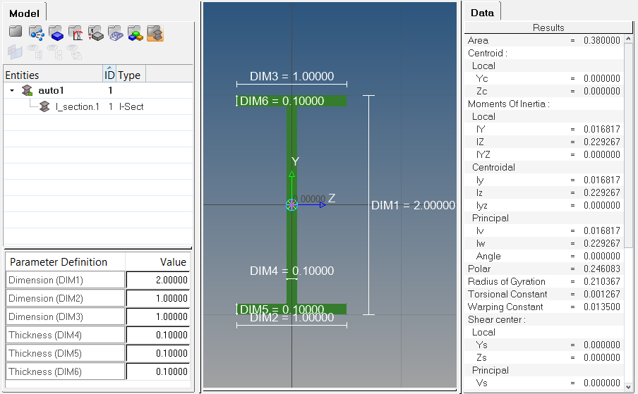
Figure 8.
Once HyperBeam solves the cross sectional properties, it is necessary to attach the beam section to a PBARL card image. This can be done by creating a component and assigning it a property that references the PBARL card image and beam section.
-
Define the property in the embedded Entity Editor.
- In the Name field, enter pbarl.
- For Card Image, select PBARL.
- For Beam Section, click .
- In the Select Beamsection dialog, select I_section.1 and click OK.
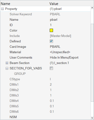
Figure 9. -
After the new component and property are created with the beam section
attached, the bar element can be defined in the Bars panel in the 1D
menu-page.
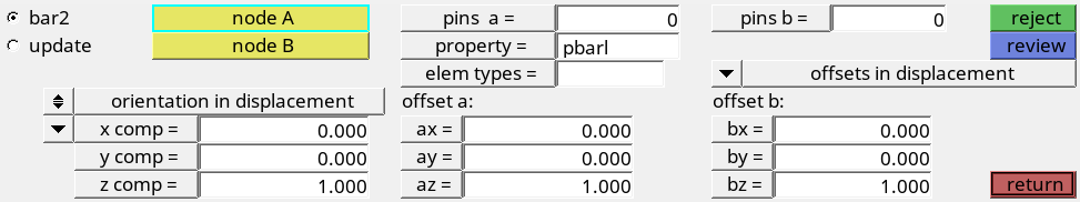
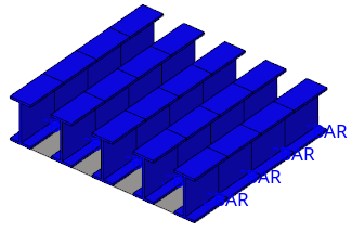
Figure 10. Bars PanelBar element alignment using HyperBeam sections is very straightforward since standard sections are defined using an absolute y-direction. The direction specified in the Bars panel defines the alignment of the beamsection’s y-direction. In this case, the positive z-direction in the Bars panel will align with the y-direction of the HyperBeam section. Since the centerline of a 1D beam element is defined about the section’s shear center, elemental offsets are frequently required. In this case, we have added z-offsets at both ends of each element to align the I-beams flush with the plate.
To fully visualize the 1D element in HyperMesh, find the display option in the Visualization toolbar (
 ).
).
Example: Create and Assign a Shell Section
Create and assign a shell section to an OptiStruct PBAR property.
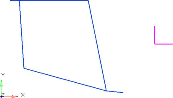
Figure 11. . The blue lines are plot elements denoting the beam section. Elements or lines can be used to describe a beam cross section. The purple lines are plot elements used to align the section within HyperBeam.
-
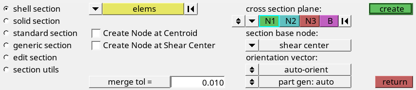
Under cross section plane, toggle to the plane and vector selector.
-
Select N1, N2, and N3 locations.
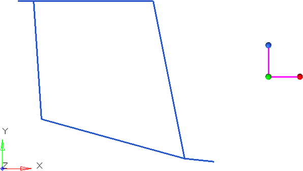
Figure 12.The vector created by N1 to N2 describes the local y-axis used in HyperBeam. N3 describes the positive sense of the z-axis. It is important to note the alignment of the local axes at this point. Later, it will be necessary to know this when the beam section is aligned for bar elements.
-
Click create.
The HyperBeam View is invoked.
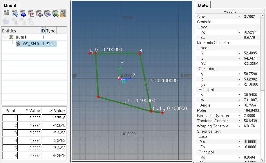
Figure 13.
Once HyperBeam solves the cross sectional properties, it is necessary to attach the beam section to a PBAR card image. This can be done by creating a component and assigning it a property that references the PBAR card image and beam section.
-
Define the property in the embedded Entity Editor.
- In the Name field, enter pbar.
- For Card Image, select PBAR.
- For Beam Section, click .
- In the Select Beamsection dialog, select OS_SH.0 and click OK.
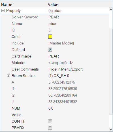
Figure 14. -
After the new component and property are created with the beamsection attached,
the bar element can be defined in the Bars panel in the 1D menu-page.
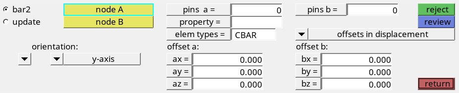
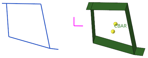
Figure 15. Bars PanelBar element alignment using HyperBeam sections is very straightforward if the section has been defined using an absolute y-direction. The direction specified in the Bars panel defines the alignment of the beamsection’s y-direction. In this case, the positive y-direction in the Bars panel will align with the y-direction of the HyperBeam section.
To fully visualize the 1D element in HyperMesh, find the display option in the Visualization toolbar (
).