Entity Selector
Entity selectors allow you to indicate which entities are to be modified when a function is performed.

Figure 1. Entity Selector
To change the data type, click the entity selector switch to access the pop-up menu of possible data types and select the type you want to use.
In addition to selecting one entity at a time on the screen, you can select multiple entities via quick window selection (hold down the Shift key and drag your mouse to create a window).
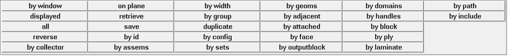
Figure 2. Extended Entity Selection Window
These selection options display for all of the entity types supported in the active client. Selections that are not valid for the current entity type are grayed out.
If you want to reset the entity selections, click the reset button to deselect all selected entities.
If the data type is a line list, click the data type of the entity selector to see the selected entities in the order in which they were selected.
- by list
- Allows you to pick the nodes individually from the node list.
- by path
- Allows you to select a few nodes that form a path, which will be used to automatically select all the displayed nodes that lie in the shortest path of the nodes selected. If you select nodes on the edges of a part, the function tries to find the closest path along the edges of that part. By path follows the connectivity of the elements between the nodes selected. Therefore, if the nodes selected are not connected by elements, this function does not apply.
- show node order
- Allows you to view the nodes currently stored in the nodelist collector by numbering the nodes in the sequence of their selection.
- by window
- Allows you to select nodes by window and internally the order of the nodes selected is determined based on its spatial location and element connectivity (if connecting elements exist).
- by list
- Allows you to select lines or surface edges individually in the desired sequence.
- by path
- Allows you to pick surface edges (two or more) and selects all the surface edges that fall in the closest path connecting the selected edges. If you select two free (red) edges, the function tries to find the closest path along the free surface edges. Since this function uses the connectivity of the surfaces, it only works with surface edges and not with free unconnected geometric lines.
Extended Entity Selection Menu
The extended entity selection menu provides a number of entity selection options.
Figure 3. Entity Selector
Figure 4. Extended Entity Selection Menu
| Option | Description |
|---|---|
| by window | Select entities inside a user-defined multiple-sided polygon in the plane of the screen. Selecting by window activates the Build Window panel. Select points in the graphics area to define a window enclosing the pick handles of the desired entities. Click select entities to highlight the enclosed entities. Alternatively, click reject entities to deselect enclosed entities that were previously highlighted. |
| displayed | Select all of the entities currently displayed on the screen. When disp is selected, all entities within collectors that are active in the disp (display) panel are selected. |
| all | Select all entities of the specified type. When you select all, the set to be added to the user mark includes entities displayed and those not displayed. |
| reverse | Allows for a Boolean "not" to be performed on the currently displayed elements. When reverse is selected, all selected elements are removed from the mark; all elements which are not on the mark and are currently active are selected. |
| by collector | Select elements, lines, surfaces, loads, coordinate systems,
vectors, equations, and points by collector. When you select by
collector, Engineering Solutions displays a list of the
available collectors. You may select multiple collectors from
this list. If you select component collectors in regard to elements or lines, the elements or lines contained in the selected components are selected. With all other entities, the entities selected by this operation are those attached to the selected component. |
| on plane | Select a group of entities whose pick handles reside on a plane. This is useful when you want to apply constraints to a plane. |
| retrieve | Retrieve previously saved entities from the user mark. Entities can be saved to the user mark by selecting save in this pop-up window, or by selecting save failed in the Check Elems panel. |
| save | Save the currently selected entities to a holding area known as the user mark. |
| by id | Select entities by typing in their ID numbers. When you
select by id, a pop-up window prompts you
to type ID numbers or ranges of ID numbers. You can use
keywords to specify a range that determines which entities
are selected. The standard format is: Examples of valid by id expressions:
You can also use a comma to separate individual entities or entity ranges. Examples of valid lists of
by id expressions:
|
| by assems | Select entities by assembly. When you select by assems, Engineering Solutions displays a list of the available assemblies. You may select multiple assemblies from this list. |
| by width | Select surfaces by width, either by picking a sample surface or by specifying a range of values for the width. |
| by group | Select entities by group. When you select by group, Engineering Solutions displays a list of the available groups. You may select multiple groups from this list. |
| duplicate | Duplicate the currently selected elements, lines, surfaces, or points. When you select duplicate, a pop-up window allows you to choose a component for the newly created duplicate entities. Select current to place the new entities in the currently active component collector. Select original to place the new entities in the same component collectors as the original entities. The initially selected entities are deselected when the duplicate elements are created and selected. This can be very useful when you use the reflect function on a model (only available for elements and lines). |
| by config | Select elements by configuration and type. When you select by config, Engineering Solutions displays a panel for specifying an element configuration and type for selection. The element type is dependent on the template file. |
| by sets | Select the entities within a set. When you select by sets, Engineering Solutions displays a list of the available sets from which you may select. Sets are created in the Entity Sets panel. |
| by geoms | Select the entities which are associated to a surface or solid. When you select by geoms, Engineering Solutions displays a panel from which you may select one or more surfaces or solids. Once the geometric entities have been picked, click add to selection or subtract from selection. Engineering Solutions selects the entities which are associated to the selected geometry. You can associate entities to a surface in the Node Edit panel. |
| by adjacent | Select entities adjacent to the entities already selected. When you select by adjacent, Engineering Solutions includes the entities that are adjacent to the entities already selected. |
| by attached | Select entities by specifying an entity among a large group of continuously connected elements. When you select by attached, Engineering Solutions includes the entities currently displayed that are attached to the entities already selected. Entities that are not displayed will not be selected although they may be attached to the entity selected. |
| by face | Select entities (nodes, elements) by surface face. It finds entities that are attached to each other without crossing a feature line. The feature angle parameter in the Options panel’s mesh and geometry subpanels determine the feature lines. Attached, adjacent surfaces or elements are progressively selected when the angle between them is less than or equal to the specified feature angle. |
| by output block | Select the nodes, elements, comps, systs, groups and mats within an outputblock. When you select by output block, Engineering Solutions displays a list of the available output blocks from which you may select. Output blocks are created in the Output Blocks panel. |
| by domains | Select entities associated with a morph domain. When you select by domains, Engineering Solutions displays a new panel in which you can pick and select the desired domains. |
| by handles | Select entities associated with morphing handles. When you select by handles, Engineering Solutions displays a new panel in which you can pick and select the desired handles. |
| by block | Select entities associated with one or more block entities. When you select by block, HyperMesh displays a new panel in which you can pick and select the desired blocks. |
| by ply | Select entities associated with one or more ply entities. When you select by ply, Engineering Solutions displays a new panel in which you can pick and select the desired plies. |
| by laminate | Select entities associated with one or more laminate entities. When you select by laminate, Engineering Solutions displays a new panel in which you can pick and select the desired laminates. |
| by path | Pick multiple nodes or lines, and selects all the nodes/lines that fall in the closest path connecting the selected ones. If you select two nodes on a free edge of some elements, the function tries to find the closest path along that free edge. This function uses the connectivity of the elements between the nodes, and thus requires the selected nodes to be part of a continuous shell mesh. Similarly, by path for lines uses the connectivity of surfaces/solids and thus requires the selected lines to be surface/solid edges. |
| by include | Select FE entities such as elements, loads and groups that
belong to selected include. When you select by
include, Engineering Solutions displays a
list of the available includes that you may select. Note: Includes created via the
Model Browser are only valid for
solvers that support them.
|
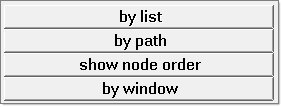
Figure 5.
| Option | Description |
|---|---|
| by list | Select nodes individually in the desired sequence. |
| by path | Pick nodes (two or more) and selects all the nodes that fall in the closest path connecting the selected nodes. If you select two nodes on the free edge of the elements, the function tries to find the closest path along the free edge. This function uses the connectivity of the elements between the nodes and thus requires the selected nodes to be part of a continuous shell mesh. |
| show node order | Review the nodes currently stored in the nodelist collector by numbering the nodes in the sequence of their selection. |
| by window | Select nodes by window and internally, the order of the nodes selected is determined based on its spatial location and element connectivity (if connecting elements exist). |
| Option | Description |
|---|---|
| by list | Select lines or surface edges individually in the desired sequence. |
| by path | Pick surface edges (two or more) and selects all the surface edges that fall in the closest path connecting the selected edges. If you select two free (red) edges, the function tries to find the closest path along the free surface edges. Since this function uses the connectivity of the surfaces, it only works with surface edges and not free unconnected geometric lines. |
Card Filter
Use the Card Filter to restrict the list of entities displayed when you click the entity selector.
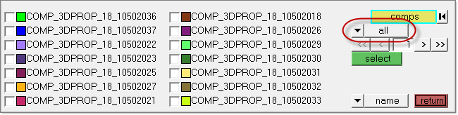
Figure 6. Card Filter. Card Filter is outlined in red.
Some panels present a list of entities when you click their Entity Selector button instead of the Extended Entity Selection options.
| Assembly | Beamsection collector | Blocks |
| Component | Contact surfaces | Control volume |
| Curves | Ddvals | Groups |
| Laminates | Load collector | Load steps |
| Material | Multibodies | Plies |
| Plots | Property | Sensors |
| Sets | Shapes | System collector |
| Tags | Titles | Vector collector |

Figure 7.
This displays a read-only text field adjacent to the Card Filter control. Click card to open a pop-up window that lists all of the cards defined in your model for the selected type of entity, and pick the card that you wish to filter by.
Once selected, only entities with the chosen card type will display in the entity list on the panel.
To remove the filter, simply use the switch to select all, displaying all entities regardless of card association, or no card, displaying only those entities that do not have a card at all.
Select Nodes on Geometry or Elements
Node and node list entity selectors allow you to not only select existing nodes in the model, they also allow you to create new nodes on geometry or on elements.
You can create a node on geometry by holding the left mouse button down along the geometry handle until the cursor becomes a square and then selecting the geometry (lines, edges, surfaces) on which you would like to place a node. Then, move your cursor to the exact location on the geometry where you would like the node to be placed and click the left mouse button to place a node. You can create nodes on elements by holding the left mouse button down on an element handle until the cursor becomes a square and selecting the element. Then, move the cursor to the exact location on the elements of that component and click the left mouse button to place the node.
-
Select new nodes on geometry.
-
Position the cursor on a node and press the left mouse button.
The cursor becomes a small white box
 .
.
-
Position the cursor on a node and press the left mouse button.
-
Select new nodes on elements.
Select Entities in the Modeling Window
After you select the correct data type, you can use the mouse to select the desired entities in the modeling window.
The graphics engine allows you to select entities by moving the mouse anywhere along the entity of interest. For lines and surfaces, it is much easier to work when you are zoomed in on a particular area, as you are not required to have a pick handle on the screen in order to pick the entity.
Another key feature in the graphics engine is the method by which nodes are selected. To select a node, select the element to which the node of interest is attached. Engineering Solutions selects the node closest to the point where the element was selected. The benefit of this feature is that it allows you to create zero length elements between two coincident nodes in a mesh.
For nodes that are not attached to any elements, Engineering Solutions allows you to select the node by picking the "node sphere" on the screen.
Each type of entity has a pick handle that allows you to select the entity.
| Entity | Pick Handle | ||
|---|---|---|---|
| Nodes | The pick handle for a node is located at the node. To select a node, move the mouse to the location on the screen where the node resides. If you need to select nodes on geometry or on an element where nodes do not currently exist. | ||
| Elements | Shell and solid element pick handles are displayed as
pixels at the centroid of the element. 1D element pick
handles are displayed as letters at the centroid of the
elements:
Click the Display Element Handles icon on the Display toolbar to switch the display of element handles on or off. Element handles can be selected whether or not they are displayed. |
||
| Lines | Each segment of a line has pick handles along its length.
Each pick handle is displayed as a small "+." If there are
many pick handles, a "+" is displayed at only some of the
pick handles. Click the Display Element Handles button on the Display toolbar to switch the display of element handles on or off. |
||
| Surfaces | Surfaces do not have pick handles. Surfaces can be selected along their edges or on interior UV lines, also known as surface lines. | ||
| Components | Components do not have pick handles. A component can be selected by picking an element, line, or surface within that component. | ||
| Systems | The pick handle for a coordinate system is located at the origin of the system. | ||
| System Collectors | System collectors do not have pick handles. To select a system collector, simply select a system within that system collector. | ||
| Loads | The pick handle for a load is located at the pick handle of the entity to which the load is applied. | ||
| Load Collectors | Load collectors do not have pick handles. To select a load collector, simply select a load within that system collector. | ||
| Plots | A plot can be selected by picking within its border. | ||
| Blocks | Blocks do not have pick handles. Blocks are drawn in shaded mode with transparency and can be selected by picking anywhere on the entity. | ||
| Titles | A title can be selected by picking within its bounding box. | ||
| Vectors | Vector pick handles are located at the arrow tip of the vector. | ||
| Curves | A curve can be selected by clicking anywhere along the curve. |