View Option Toggle Buttons
Figure 1.
Figure 2. Active
Figure 3. Inactive
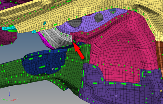
Figure 4. . Notice the small, white-highlighted connector entity on the grey-meshed part. (Model provided courtesy of Audi)
| Option | Name | Effect |
|---|---|---|
| 1st connector entity | The selected connector entity can always be seen as the 1st
connector entity, even if the selected connector doesn’t
reference any links at all. If the 1st connector entity view
option button is active, the selected connectors will be taken
into account for the action regardless. This means that in the
case of isolation, all selected connectors will be
isolated.
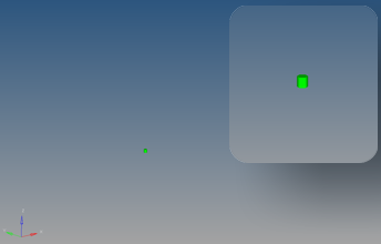 Figure 5. . The single selected connector is isolated (also shown in magnified view). |
|
| Linked entity | Finds the link entities/supported entities to which the
selected connector connects. If this linked entity view option button is active, all entities linked to the 1st connector entities will be taken into account for the action. It does not matter if the 1st connector entity view option button is active or inactive, its entities will still be located. This determination has nothing to do with any display states. This means that in case of isolation, only the
entities which are referenced by the selected connectors
(1st connector entity) are isolated.
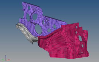 Figure 6. . The connector does not display because "1st linked entity" is not active. |
|
| 2nd connector entity | Finds other connectors that are connected to the chosen
connectors' linked entities. If this 2nd connector entity view option button is active, all connectors referenced by the determined linked entities except the originally-selected 1st connector entities will be taken into account for the action. It does not matter if the 1st connector entity or the linked entity view option buttons are active or inactive; this determination has nothing to do with any display states. In the case of isolation, this means that only the connectors that share links with the selected 1st connector entities are isolated.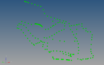 Figure 7. . The entity does not display because "linked entity" is not active. |
|
| Realization | Finds and displays the realization for the selected
connectors.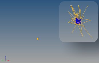 Figure 8. |
Cumulative Effect of Multiple View Options
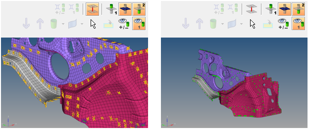
Figure 9. . The first image shows an isolated view with linked entity, 2nd connectors, and realizations. The second includes the same options, but without realizations.
Using Connector Links to Expand the Selection
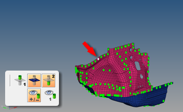
Figure 10. . The highlighted connector is selected for Show.
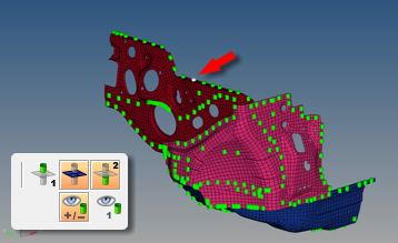
Figure 11. . A new connected component displays. Again, the highlighted connector is clicked...
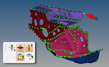
Figure 12. . Connected component displays. A third highlighted connector is clicked...
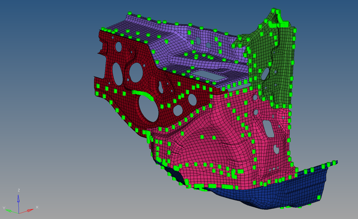
Figure 13. . Third connected component displays.
You can continue revealing more and more parts this way, theoretically eventually revealing the entire model. The reverse option is also true; by activating the Hide mode instead of Show, you could gradually "chip away" at the model, removing one connected component at a time – or multiple components in the case of multi-layer connectors.