Specify a periodic boundary condition (PBC) to analyse infinite periodic
structures.
On the Construct tab, in the Structures
group, click the Planes/arrays icon. From the drop-down list, select Periodic boundaries.
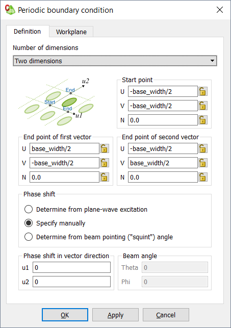
Figure 1. The Periodic boundary condition dialog.
From the Number of dimensions list, select one of the
following:
To create a one-dimensional PBC where the unit cell is repeated along a
line, select One dimension.
To create a two-dimensional PBC where the unit cell is repeated to form
a surface, select Two dimensions.
To remove the PBC from the model, select No periodic
boundary.
Under Start point, specify the start point of the
vector.
Under End point of first vector, specify the end point
of first vector.
Under End point of second vector, specify the end point
of the second vector.
Under Phase shift, select one of the following:
When a plane wave is used as excitation, the phase difference between
the cells cannot be specified. To determine the phase shift of the
excitation, select Determine from plane-wave
excitation.
To specify the phase shift, select Specify
manually.
In the u1 field, specify the phase shift in
the first direction, u1.
In the u2 field, specify the phase shift in
the second direction, u2.
To specify the theta and phi angle of the “squint” angle, select
Determine from beam pointing (squint) angle.
In the Theta field, specify the theta angle
of the “squint” angle.
In the Phi field, specify the phi angle of
the “squint” angle.
Click OK to define the PBC and to close the
dialog.
 Planes/arrays icon. From the drop-down list, select
  Periodic boundaries.