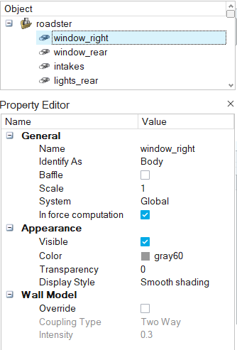
The Property Editor shows all the properties of
a selected object and enables you to edit
them.
The Property Editor can be opened and closed in the following ways:
Click View > Property Editor from the menu bar
Press F3
Right-click on selected objects and choosing
Properties/Hide Properties from the context menu
Properties that are not editable appear grayed out. Properties such as a name and color can be
assigned to various objects, such as parts, or to an entire model. If multiple objects are
selected, the values of properties which are the same for the selected objects are displayed
in the Property Editor, and the values of properties which are not the
same are left blank. If you change a value in the Property Editor, the new
value is assigned to all selected objects. Figure 1.
Supported Properties
The properties assigned to an object vary based on the type of object.
General
Name
Object name. Objects can be renamed in the Model Browser or
Property Editor, or by using the right-click context menu.
Identify As
Part type in terms of wind tunnel testing: body, heat exchanger in/out/wall, or
wheel. This option is also set by means of the Identify Parts
tool and the right-click context menu.
Baffle
Baffles are two dimensional surfaces that are surrounded by fluid on all sides but
do not combine with other surfaces to form a fluid volume. They are used to represent
thin regions of solid material that are too costly to explicitly resolve. This option
is also set by means of the right-click context menu.
Scale
The scale factor of the part with respect to the original geometry that was imported
into Virtual Wind Tunnel. This option is also set by means of the Scale tool.
Group (heat exchanger, wheels)
Identifies which wheel or heat-exchanger group this part belongs to. You can select
different groups from the drop-down list.
Appearance
Visible
Indicates whether the selected object is visible (shown or hidden) in the modeling window.
Color
Indicates the color assigned to the object when it is displayed in the modeling window.
Click to create and assign custom
colors.
Transparency
Transparency of the selected object, according to a percentage. By default, objects
are zero percent transparent.
Display Style
Indicates how parts and assemblies are displayed in the modeling window. In addition to the default smooth shading display
style, each part can be displayed as mesh lines, or as smooth shading with mesh
lines.
Inflow Velocity (Wind Tunnel Only)
Inflow speed
The velocity of air at the inlet to the wind tunnel. This velocity is also used as
the wall velocity of belts and moving ground if activated.
Boundary Layer Suction (Wind Tunnel Only)
Active
Activates the modeling of a boundary layer suction upstream of the point at which
the boundary layer begins to grow.
Location Reference
The reference location from which boundary layer suction distance is measured. This
can be the origin or the wind tunnel's inflow.
Distance
The distance from the reference location at which the boundary layer suction is
applied.
Tunnel Properties (Wind Tunnel Only)
Length
Total length of the wind tunnel, typically designated in meters.
Width
Total width of the wind tunnel, typically designated in meters.
Height
Total height of the wind tunnel, typically designated in meters.
Tunnel Extents (Wind Tunnel Only)
X Min, X Max, Y Min, Y Max, Z Min, Z Max
This value indicates the extension of the wind tunnel with respect to each
coordinate axis.
This is different from the Length, Width and Height settings in that it can comprise
positive and negative values. For example, a wind tunnel that is four meters wide
across its Y axis, but centered on the coordinate origin, would have a Y Min of -2m
and a Y Max of 2m.
Heat Exchanger Properties (Heat Exchangers Only)
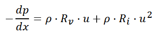
Inertial Resistance
The inertial resistance coefficient () used
to determine the pressure drop across the porous media per the following
equation:
Where,
Density
Velocity
Pressure
Location coordinate
Viscous Resistance
The viscous resistance coefficient () used
to determine the pressure drop across the porous media per the following
equation:
Where,
Density
Velocity
Pressure
Location coordinate
Permeability Direction (Heat Exchanger Only)
Direction X,Y,Z
Defines the direction in which the permeability is applied.
Wheel RPM (Wheels Only)
Auto Calculate
Automatically calculate the angular velocity of the wheel based on the wind speed
and location of wind tunnel ground plane.
Angular Velocity
Rate of rotation of the wheel.
Wheel Center (Wheels Only)
Wheel Center X, Wheel Center Y, Wheel Center Z
Location of the wheel's center in the global coordinate system. The default center
is computed based on the oriented bounding box of the part.
Wheel Axis (Wheels Only)
Wheel Axis X, Wheel Axis Y, Wheel Axis Z
Wheel's axis of rotation in the global coordinate system. The default axis is
computed based on the oriented bounding box of the part.
Fan Rpm (Fans Only)
RPM
Rate of rotation of the fan.
Fan Center (Fans Only)
Fan Center X, Fan Center Y, Fan Center Z
Location of the fan's center in the global coordinate system. The default center is
computed based on the oriented bounding box of the part.
Fan Axis (Fans Only)
Fan Axis X, Fan Axis Y, Fan Axis Z
Fan's axis of rotation in the global coordinate system. The default axis is computed
based on the oriented bounding box of the part.
 to create and assign custom
colors.
to create and assign custom
colors. ) used
to determine the pressure drop across the porous media per the following
equation:
) used
to determine the pressure drop across the porous media per the following
equation: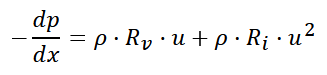


 ) used
to determine the pressure drop across the porous media per the following
equation:
) used
to determine the pressure drop across the porous media per the following
equation: