Submitting a Job
Define and run an analyis using the Run Analysis tool.
The model setup should be completed before submitting job for analysis. Save the model in a new folder with the desired project name. Analysis will be performed in this folder based on user preference under Run Options.
-
Click
 on the Analysis tool in the
Run group.
on the Analysis tool in the
Run group.
-
In the Analysis Parameters dialog, define parameters
accordingly.
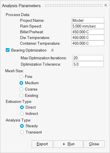
Analysis Parameters Settings
- Project Name
- The data deck is written with "name" as a prefix. It is written in the same folder where the model is saved. Avoid using special characters as files will be created using this name.
- Ram Speed
- Ram velocity. The speed of the punch (also referred to as ram or dummy block).
- Billet Preheat
- Used as the initial condition for the analysis for transient runs, and as initial guess for steady state analysis.
- Die Temperature
- Used to specify the heat transfer condition at the workpiece and die interface.
- Container Temperature
- Used to specify the heat transfer condition at the container and billet interface.
- Alloy
- Alloy used for extrusion. The workpiece material and billet are made with this material.
- Bearing Optimization
- Check this box to include bearing optimization in the simulation. Specify Max Optimization Iterations and Optimization Tolerance to control speed and accuracy.
- Mesh Size
- Medium is the preferred option. If the model has many fine features, selecting fine is recommended. If it is a simple model, coarse option can be used. To start from existing mesh, click on Existing and select the mesh file.
- Extrusion Type
- Direct. Dummy block moves at the ram speed.
- Analysis Type
- Steady State. Default selection.
- Coupled Analysis
- No Select no to opt of running Coupled Analysis.
- Advanced Parameters
- For a fast and reasonably accurate analysis, nonlinear iteration tolerance can be increased to 0.005 or even 0.01. For steady state analysis, default values yield more accurate results.
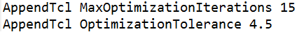
- Other advanced parameters can be updated using the file
AdditionalParameters.txt. Place this file in your project
folder. The format to follow
is:
AppendTcl <parameter_name> value
Sample AdditionalParameter.txt