The goal of this process is to classify extracted bearing lines into different groups.
Lines in a group are assigned the same initial bearing length and are optimized
identically. For example, all lines in Group 1 will have the same initial length and will
have the same length after each optimization iteration.
There are some special groups that do not adhere to this rule. These are:
Independent: All the lines are independent, that is, each one
of them will have their own unique length and they will optimized by the solver
independently. These lines will be green in color. This group cannot be deleted by the
user, however, it can be empty. Initially all lines are assigned to this group.
Fixed: All the lines are independent and have a fixed length,
that is, length of these lines will not be changed by the solver. These lines will be
dark blue in color. This group cannot be deleted by the user, however, it can be empty.
Ignored: All the lines in this group are ignored by the
interface and they will not be exported. These lines are grey in color. This group
cannot be deleted by the user, however, it can be empty.
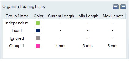
Group Attribute
As shown in the above image, each group will have current, minimum, and maximum length
data. If the lengths of the line in a group are different, the length of the last line will
be used as reference. You can change this value, and the value in the table will be used
while exporting the model. However, length of the lines in the modeling window will not be adjusted to reflect this. The modeling window will always retain the original length. This enables you to
have their original length for reference.
Current Length: Current length of the group. This is the length
of the bearing line which is recently added to the corresponding group.
Min Length: Minimum length of the group. This is 75% of the
current length; minimum value should not be less than 1mm.
Max Length: Maximum length of the group. This is 125% of the
current length; maximum value shouldn’t exceed the length of the bearing solid.
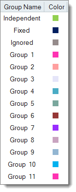
Color Codes
Bearing optimization uses standard colors for various groups, these color codes are fixed.
These colors do not have any special meaning and intended only for visual differentiation.
For all user groups, a set of standard 10 colors will be used. They will repeat
cyclically after group number 10.
Grouping Bearing Lines
It is not necessary to group all the lines to complete the setup. Lines that are not
grouped will be treated as independent lines.
From the Organize Bearing Lines dialog, select any one
group.
In the modeling window, select a bearing line.
The selected line moves to the active group and becomes highlighted to
represent the current group.
Double-click or press Enter to exit the active group.
Tip: You can select multiple lines using window selection methods.
Removing a Bearing Line from a Group
From the Organize Bearing Lines dialog, select the group
with the bearing line to remove.
All the lines in that group are highlighted.
Click on the bearing line to remove.
The selected bearing line is released from the current group and marked
as independent. The color of the line changes back to green.
Adding a New Bearing Line
From the Organize Bearing Lines dialog, select the
destination group.
Click on the bearing line to move.
The selected bearing line is moved from the current group to the
destination group.