HM-2090: Edit Dimensions
In this tutorial you will learn how to create and edit dimensions on geometry using the Dimensioning tool.
This tool is used to change one or more dimensions of existing geometry, thus changing the basic shape of solids and other enclosed volumes. With the dimensioning tool, you can select dimensions of or between surfaces, and modify those dimensions as required with the use of dimension manipulators.
This exercise uses the 2_holes.hm file, which can be found in the hm.zip file. Copy the file from this directory to your working directory.
Open the Model File
In this step you will open the model file, 2_holes.hm.
- Start HyperMesh Desktop.
- From the menu bar, click .
- In the Open Model dialog, open the 2_holes.hm model file.
Create a Dimension
In this step you will create a dimension for the thickness of a part.
-
In the Feature dialog:
- For Point1, click Unspecified >> Point.
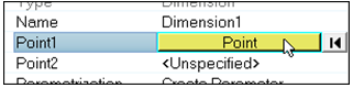
Figure 1. - Select point1 as indicated in the image that follows, then click
proceed in the panel.Note: If there are no visible fixed points on your model, verify that
 is selected on the Display
toolbar.
is selected on the Display
toolbar. - For Point2, click Unspecified >> Point.
- Select point2 as indicated in the image that follows, then click
proceed in the panel.
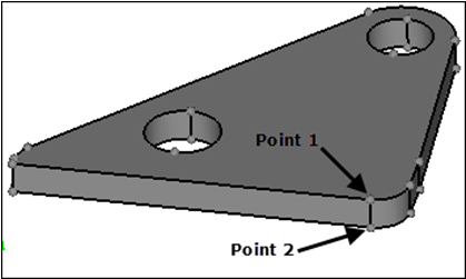
Figure 2. - For Parameterization, leave it set to the default Create Parameter value.
- Click Create.
A dimension feature (Dimension1) and an associated parameter (Dimension1) are created. A dimension manipulator with a value of 0.375 is created between the two points to represent the thickness of the part.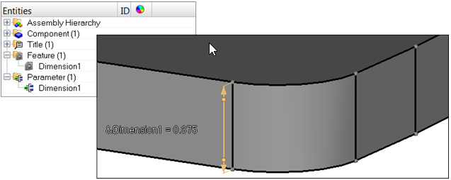
Figure 3. - For Point1, click Unspecified >> Point.
-
Repeat step 2 to create a second dimension feature for the hole. Select the
points indicated in the following image.
A dimension feature (Dimension2) and an associated parameter (Dimension2) are created. A dimension manipulator with a value of 0.875 is created between the two points to represent the diameter of the hole.
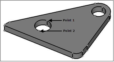
Figure 4. -
Repeat step 2 to create a third dimension feature for the other remaining hole.
A dimension feature (Dimension3) and an associated parameter (Dimension3) are created. A dimension manipulator with a value of 0.75 is created between the two points to represent the diameter of the hole.
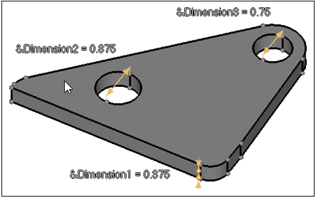
Figure 5.
Change the Dimension Value
In this step you will change the dimension value.
-
Click the dimension value (0.375) of the dimension manipulator and type
0.25 in the editable field.
The part's thickness decreases.
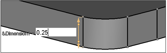
Figure 6. -
In the Entity Editor, Double value field, change the
value from 0.215 to 0.5.
The part thickness increases.
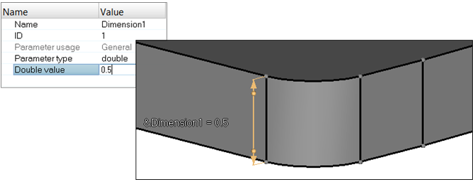
Figure 7.
Modify the Dimension Manipulator
In this step you will modify the dimension manipulator direction.
-
Select the line indicated in the following image.
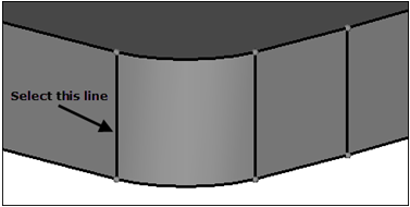
Figure 8. -
Click create.
HyperMesh creates two nodes that will be used to show the starting position of the thickness during future modifications.
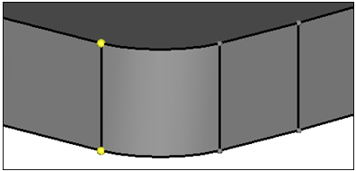
Figure 9. -
In the Entity Editor, Double value field, change the
value from 0.5 to 1.0.
The part's thickness increases equally about the midpoint between the original locations.
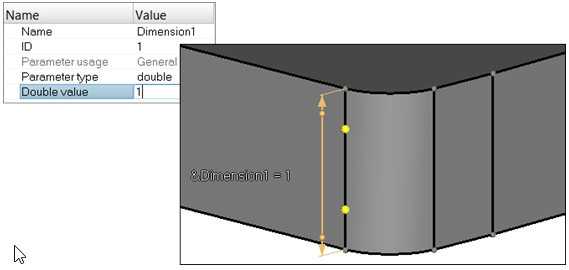
Figure 10. -
Undo the change by clicking
 from the Undo/Redo toolbar.
-
Select the handle at the bottom of the dimension manipulator as indicated in
the following image.
The bottom arrow changes to a line, which indicates that the bottom end will remain fixed.
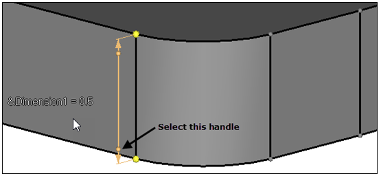
Figure 11. -
Change the dimension value again from 0.5 to
1.0.
The bottom end stays fixed.
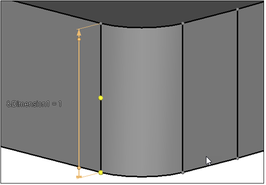
Figure 12. -
The dimension manipulator can also be locked from the Entity Editor.
- In the Model Browser, Feature folder, click Dimension1.
- In the Entity Editor, set Lock Side to Point1.
The top arrow of the dimension manipulator changes to a line, which indicates that the top end will remain fixed. The bottom end changes to an arrow, as only one end can remain fixed.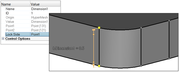
Figure 13. -
Change the dimension value again from 0.5 to
1.0.
The top end stays fixed.
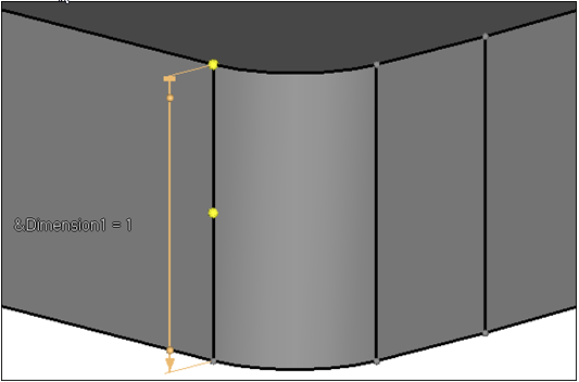
Figure 14.
Create and Modify Diameter Dimensions
In this step you will create and modify the diameter dimensions on the holes.
-
Click the dimension manipulator and change the dimension value from 0.875 to
.25.
The hole diameter decreases.
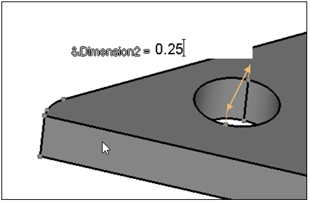
Figure 15. -
Change the dimension value from 0.75 to 1.0.
The hole diameter increases.
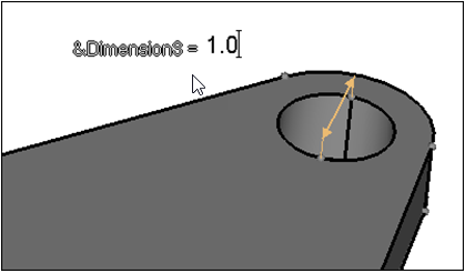
Figure 16.
Delete a Manipulator
In this step you will delete a manipulator.
-
In the Entity Editor:
-
For Expression value, type 2*Dimension2.
This expression indicates that Dimension3 is two times the value of Dimension2.
The hole's diameter is updated to 1.0, which is twice the size of the first hole's diameter. The dimension manipulator displays the full expression as &Dimension3=2*Dimension2.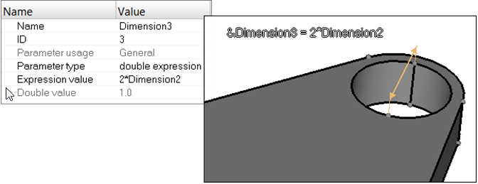
Figure 17.
-
For Expression value, type 2*Dimension2.
-
In the Entity Editor, Double value field, change the
dimension to 0.25.
The first hole's diameter decreases from 0.5 to 0.25, and the second hole's diameter becomes 0.25*2=0.5.
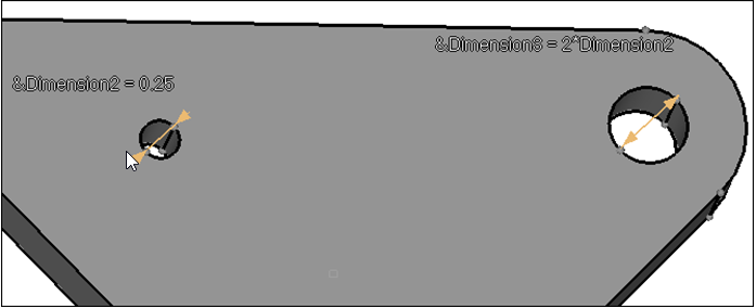
Figure 18.
Parameterize and Unparameterize the Dimension
In this step you will parameterize and unparameterize the dimension.
-
In the Entity Editor, right-click on the Value field
and select Unparameterize from the context menu.
Dimension3 becomes unparameterized, and its corresponding dimension manipulator displays the current value of the dimension feature, instead of the parameter. All changes can now be made directly to Dimension3.
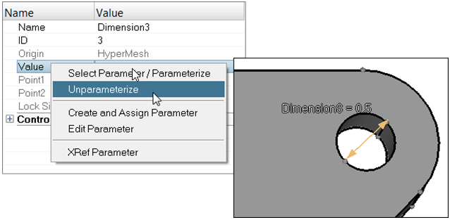
Figure 19. -
In the Select Parameter dialog, select
Dimension3 and click OK.
The hole updates with the Dimension3 parameter and displays the full expression in the dimension manipulator.
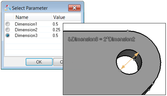
Figure 20.
Delete a Manipulator
In this step you will delete a manipulator.
Mesh the Part
In this step you will mesh the part.
-
Click mesh.
HyperMesh meshes the part.
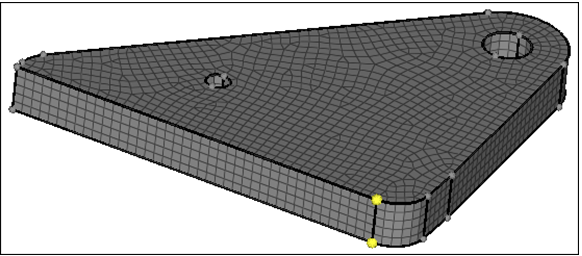
Figure 21.
Modify Dimensions with Automatic Remeshing
In this step you will modify the dimensions with automatic remeshing enabled.
-
In the Entity Editor, Double Value field, change the
value from 0.5 to 1.0.
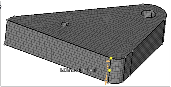
Figure 22. -
In the Entity Editor, Double
value field, change the value to
0.5.
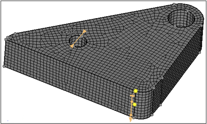
Figure 23.