HM-2050: Create Surfaces from Elements
The surfaces created in this process are regular surfaces that can be used for geometry editing (for changes to a design) and meshing, and to export geometry information (in reverse engineering applications, for example). This is particularly useful if you are trying to obtain geometry information (surfaces) from a model containing elements only.
- Generate surfaces from existing elements
- Plot elements
- Control what surfaces are created
This exercise uses the fe_to_surf.hm file, which can be found in the hm.zip file. Copy the file from this directory to your working directory.
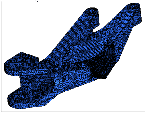
Figure 1.
Open the Model File
In this step you will open the fe_to_surf.hm model file.
Generate Shell Elements
In this step you will use the faces panel to generate shell elements on the outside of the solid mesh.
-
To return to the main menu, click return.
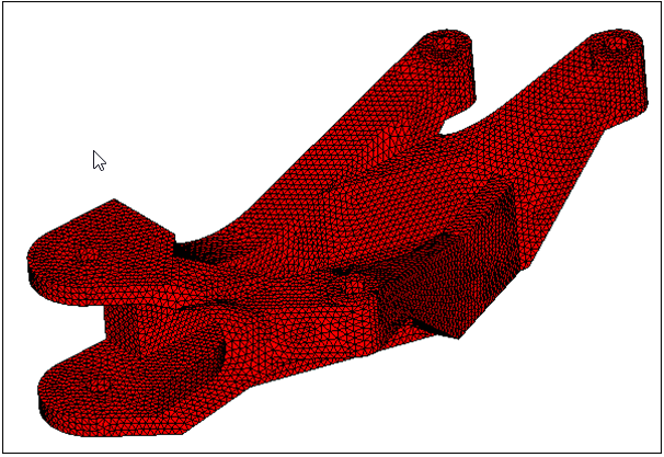
Figure 2.
Obtain Surfaces From Elements
In this step you will use the Surfaces panel and the From FE subpanel on the tria (faces) elements to obtain surfaces and understand the behavior of the panel.
-
To shade the model's geometry and surface edges, click
 on
the Visualization toolbar.
on
the Visualization toolbar.
Capture Features with Plot Elements
Delineating the surfaces to be created is an essential step in obtaining the desired surfaces. This level of control is achieved by supplying the surface generator with some plot elements, which will indicate what the boundaries of the various surfaces should be. This function works well only when the selected plot elements form closed loops.
The new surfaces should have boundaries that respect the features of the tria mesh. The tria mesh captures, to some extent, the features of the initial geometry.
Generate plot elements that correspond to the features of the mesh. You can use the edges, features, and edit element panels to create plot elements. Using the Features panel is one of the most automated ways of generating plot elements, although it does not always create the features as desired. Some manual methods will be used to modify the results of automatic feature creation.
In this step, you will use the features panel to automatically generate plot elements capturing the features of the tria mesh (^faces component). Use a break angle of 30 degrees.
-
Zoom into the areas indicated in the following image to see how many plot
elements were created to define the boundary area.
Note: In the following steps you will remove the unnecessary plot elements.
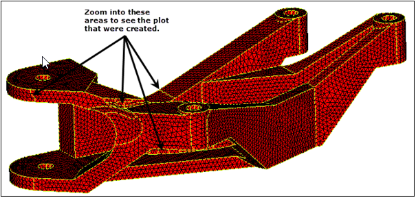
Figure 3. -
Click remove.
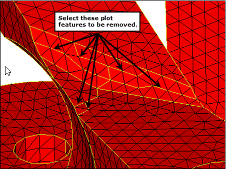
Figure 4.
Add a Delineation Feature
In this step you will add a new delineation feature.
-
Click add.
HyperMesh creates a new feature line.
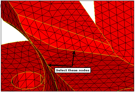
Figure 5. -
Rotate, zoom, and pan the model to locate the features created with a zigzag
pattern, as indicated in the following image.
Note: In the following steps you will delete these features and create new smooth ones.
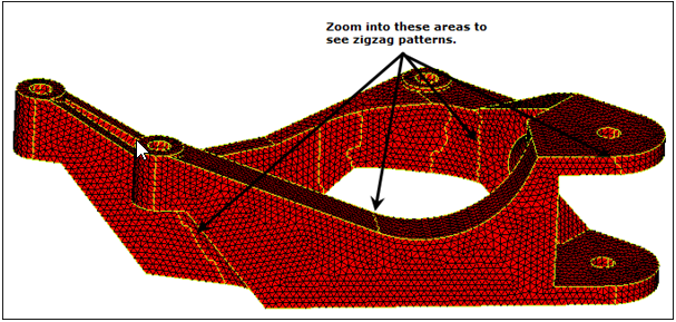
Figure 6. -
Select one of the plot elements as indicated in the image that follows.
HyperMesh selects the entire row of elements to the next intersection as you select plot elements.
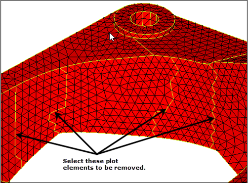
Figure 7. -
Select the nodes indicated in the following image.
HyperMesh selects all nodes in the path between these two nodes.
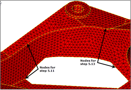
Figure 8. -
Repeat the previous cleanup operations to create features to your needs. The
following image shows an example of the final features. Notice that many of the
features in the cylindrical holes have been removed.
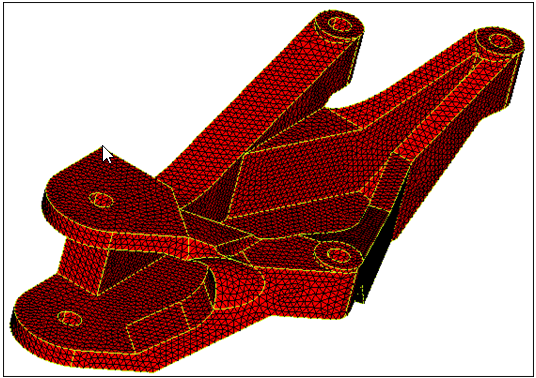
Figure 9.You created plot elements that will be used in the surfaces panel to indicate the boundaries of the surfaces to generate. These plot elements were generated in an attempt to capture the features of the tria mesh. The number and location of plot elements generated using this approach is directly dependent on the value that is chosen for the feature angle. In most situations, a lower feature angle will generate more plot elements while a higher one will yield fewer plot elements.
It is often useful to experiment with different values for the feature angle as one value may bring you much closer to the desired set of plot elements than another, significantly limiting the amount of subsequent editing required.
In this section, you learned how to create and edit plot elements using the features panel. The creation process was straightforward, but required some editing in order to obtain a set of plot elements forming closed loops only. Various tools are available to make the editing process as easy as possible and you used the ones that would allow you to get to your goal the most effectively.
Now that both the shell elements and the plot elements delineating the surfaces are available, you will generate surfaces on the entire model.
Generate Surfaces
In this step you will generate surfaces using the Surfaces panel from FE subpanel.
-
Click return.
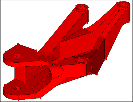
Figure 10.The surfaces generated could now be exported or used for any surface editing or meshing operation.This concludes this tutorial. You may discard this model or save it to your working directory for your own reference. As this tutorial showed, this is a powerful tool in generating surface data where none is available, but needed. It also provides you with a great deal of control over the surfaces that are generated through the use of plot elements. Automated and semi-automated ways let you create and edit plot elements quickly and easily.