HM-2035: Refine Topology
Topological details of the geometry may affect the quality of the mesh created from the surfaces.
Some of these details may not reflect any major feature of the part’s shape, and can be removed without concern. When modifying the topology affects the shape of the surfaces, a compromise must be made between the part shape and the element quality necessary for the analysis. Other times, adding topological features that do not change the shape of the part may actually help create a better quality mesh.
- Mesh the part to determine poor element quality
- Suppress small edges
- Split surfaces
- Remove interior fixed points
- Replace closely placed fixed points
- Create final mesh
This exercise uses the clip_refine.hm file, which can be found in the hm.zip file. Copy the file from this directory to your working directory.
Open the Model File
In this step you will open the model file, clip_refine.hm.
- From the menu bar, click .
- In the Open Model dialog, open the clip_refine.hm model file.
- Take a few moments to observe the model using the different visual options available in HyperMesh (rotation, zoom, etc.).
Create a Preliminary Mesh
In this step you will create a preliminary mesh.
-
Click mesh.
HyperMesh meshes the surfaces.
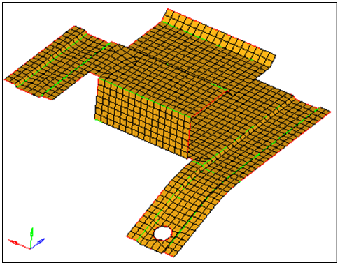
Figure 1.
Review Mesh Quality
In this step you will review the mesh quality.
-
In the Model Browser, Component folder, click
 next to Middle Surface to turn off the display of its elements.
Remove Short Edges
In this step you will remove short edges by combining fixed points.
-
Select the lower fixed point as indicated in the image below.
Note: If there are no visible fixed points on your model, verify that
 is selected on the Display toolbar.
 -
Click replace.
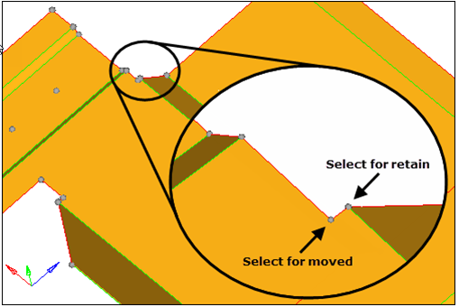
Figure 2.
Remove Fixed Points
In this step you will remove the fixed points interior to all surfaces.
You should still be in the Points panel.
-
Select the four fixed points as illustrated in the following image.
HyperMesh deletes each fixed point when you select it.
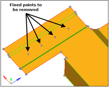
Figure 3.These fixed points are left over from a defeaturing operation where small holes (pinholes) were removed. They could remain without greatly sacrificing the element quality, given the element size used for the mesh, but the mesh would be better without them.
Add Edges to Control the Mesh Pattern
In this step you will add edges to the surfaces to control the mesh pattern.
-
With the lines selector now active, select the line shown in the image
below.
HyperMesh creates an edge from the location of the fixed point perpendicular to the line.
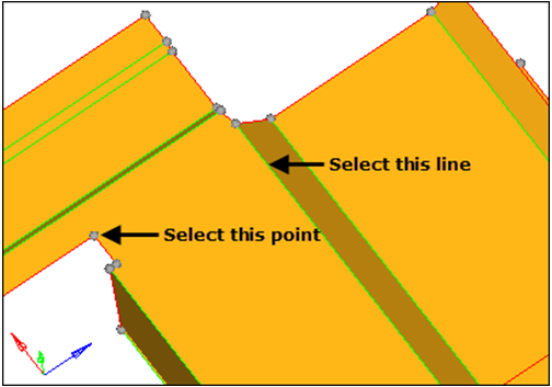
Figure 4. -
Repeat Steps 2 through 4 for the point and line illustrated in the following
image.
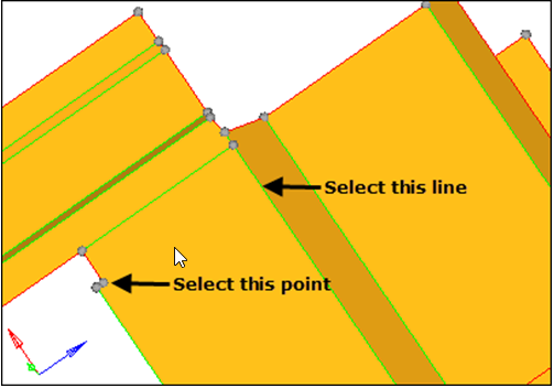
Figure 5. -
Repeat Steps 2 through 4 for the point and line illustrated in the following
image.
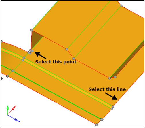
Figure 6. -
Repeat Steps 2 through 4 for the point and line illustrated in the following
image.
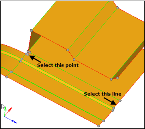
Figure 7.
Add Edges to Surfaces
In this step you will continue to add edges to surfaces to control the mesh pattern.
-
Select the five surfaces indicated in the following image.
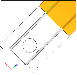
Figure 8. -
Press and hold the left mouse button, move it over the edge as indicated in the
following figure, and then release it when the cursor changes to a square with a
dot in the center
 .
.
-
Press and hold the left mouse button, move it over the edge of the hole as
indicated in the following image, and then release it when the cursor changes to
a square with a dot in the center .
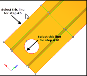
Figure 9.
Suppress Shared Edges
In this step you will suppress shared edges causing a small edge.
-
Select the five lines illustrated in the following image.
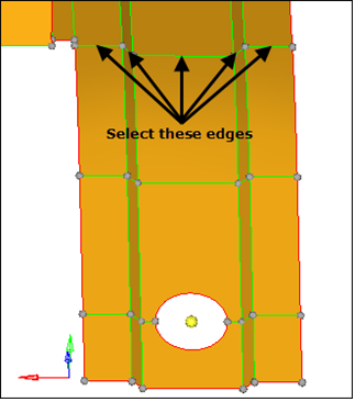
Figure 10.
Remesh the Part
In this step you will remesh the surfaces of the part using the automatic mode, a size of 2.5, and the mixed mesh type.
-
In the Model Browser, Component folder, click
next to Middle Surface to display its elements.
- To open the Automesh panel, click from the menu bar, or press F12.
- Verify that elem size = is set to 2.5 and the mesh type is set to mixed.
- To select all displayed surfaces, click surfs >> displayed.
- Click mesh.
Review Mesh Quality
In this step you will again review the mesh quality.
Save Your Work
In this step you will save your work.
The part is now meshed and ready to be set up for an analysis. Now is a good time to save your work.