HM-2070: Edit Geometry and Mesh Using Quick Edit Panel
This tutorial will explore the geometry and mesh editing functions available in the Quick Edit panel.
The Quick Edit panel provides easy access to a number of geometry editing mesh editing tools. More than a dozen functions are presented in this single panel. Many of the functions can be found in other HyperMesh panels. These tools may be used before creating the surface mesh to simplify geometry, correct geometry errors, or add additional geometric features to control the mesh generation. Additionally, if a mesh already exists on the geometry, you have the option of automatically remeshing the geometry as you modify it.
This exercise uses the base_bracket.hm file, which can be found in the hm.zip file. Copy the file from this directory to your working directory.
Open the Model File
In this step you will open the model file, base_bracket.hm.
- Start HyperMesh Desktop.
- From the menu bar, click .
- In the Open Model dialog, open the base_bracket.hm model file.
Create a Baseline Mesh
In this step you will create a baseline mesh.
-
To exit the panel, click return.
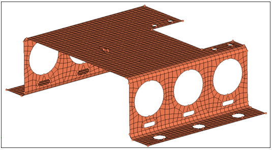
Figure 1.In the next step, you will start refining the geometry and improving the mesh quality. HyperMesh has the ability to automatically remesh a surface if any topology changes are made to the geometry. This function is controlled by a setting in the Preferences > Meshing Options panel, under topology revision. The default option is to remesh the surface; however, you can opt to keep or delete the mesh instead.For the base component, your focus will be to improve the mesh quality around the large holes in the side surface and the mounting holes on the flanges. You will remove the oblong holes and improve the mesh quality around the five small holes on the top surface by trimming in a "washer" surface around the holes.
Simplify the Geometry
In this step you will simplify the geometry by removing unnecessary holes.
-
Select the six oblong holes under the large circular holes.
HyperMesh removes them and re-generates the mesh.
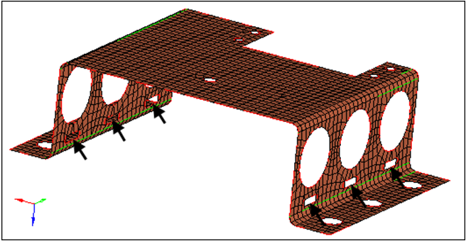
Figure 2.
Modify Geometry Around Holes that Remain
In this step you will modify the geometry around remaining small holes.
-
With the split surf-line: line selector now active, select the line indicated
in the following image. HyperMesh trims the
surface.
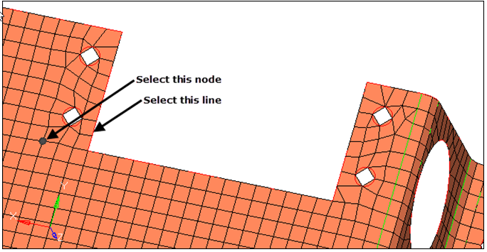
Figure 3. -
Repeat steps 4.2 through 4.3 to create four more trim lines in the locations
indicated in the following image. At the end, each of the four small holes is
isolated in its own rectangular surface patch.
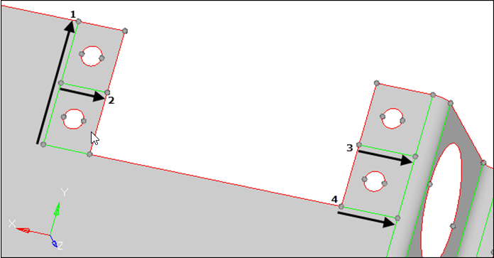
Figure 4.
Trim a Washer Layer
In this step you will trim a washer layer into the surface around each of the four holes.
-
Select the free surface edges (red edges) around the four small holes.
HyperMesh creates a washer around each hole.
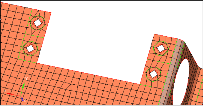
Figure 5. -
Left-click, twice, on one of the hole's inner surface edges indicated in the
following image.
HyperMesh adjusts the element density from 2 to 4.Note: Left-click a surface edge to increase the element density by one, or right-click to decrease the element' density by one.
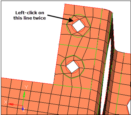
Figure 6. -
Right-click on the hole's other inner surface edge, indicated in the following
image, to apply the target density.
HyperMesh adjusts the element density from 2 to 4.
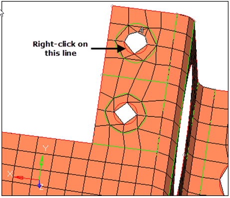
Figure 7. -
Left-click on one of the hole's outer surface edges indicated in the following
image.
HyperMesh adjusts the element density from 3 to 4.
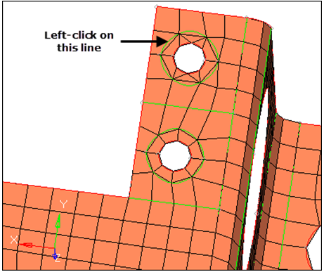
Figure 8. -
Right-click on the hole's other outer surface edge, indicated in the following
image, to apply the target density.
HyperMesh adjusts the element density from 3 to 4.
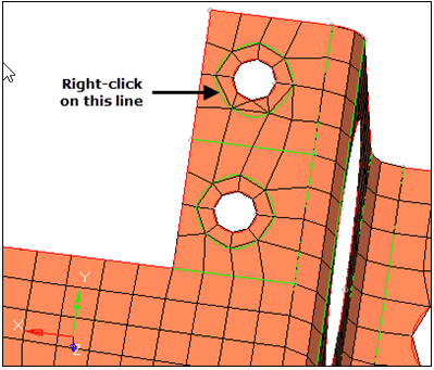
Figure 9. -
Left-click on one of the hole's surface trim lines as indicated in the
following image.
HyperMesh adjusts the trim line's element density from 3 to 4.
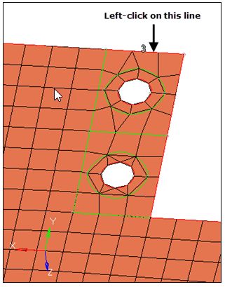
Figure 10. -
Right-click on the surface trim line, indicated in the following image, to
apply the target density.
HyperMesh adjusts the trim line's element density from 3 to 4.Note: You do not have to adjust the element density for the other trim lines that surround the hole, as they already have an element density of 4.
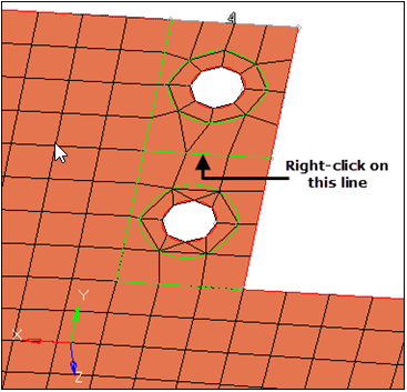
Figure 11.
Adjust the Mesh
In this step you will adjust the mesh around the large holes on the side surfaces.
You should still be in the Quick Edit panel.
-
Use the split-line function, that you learned in step 4, to trim 12 surfaces
patches around the large holes as indicated in the following image.
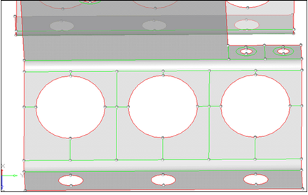
Figure 12.
Remesh Newly Trimmed Surfaces
In this step you will remesh the newly trimmed surfaces.
-
Adjust the density on the six edges across the center of the holes from 1 to
2.
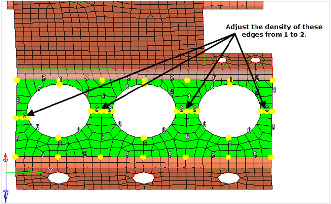
Figure 13.