Below are the steps for Manual E-Line Creation method, in
which you will be creating connector locations by selecting single or multiple
master and slave components and providing various parameters. Select
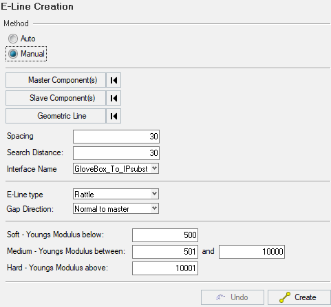
Manual radio button in Method, and
the panel will be displayed as below Manual E-line Method: t Figure 1.
You can do the following operations in the panel -
Master Component(s) - to select the master component
Slave Component(s) - to select the respective slave component for
interface creation
Geometric Lines - to select the geometric line for the selected
components
Spacing and Search Distance- numerical value to define the
spacing between the connector placements
Interface Name - to select and define a name for the interface
E-Line Type - drop down list to select the required line type. Line
types are -
Rattle
Squeak
Gap Direction - to define the gap direction with respect to master
component. SnRD supports two directions, namely:
Normal to Master - where the gap direction is perpendicular
to master component
In-plane to Master - where the gap direction is in plane, or
is not perpendicular to master component
Define the Contact Types based
on the Youngs' Modulus.
Create - after making the necessary selections, you can click
Create. This will create the connector locations
in the model
Undo - you can revok or undo the connectors created in the immediate
previous step