Auto E-Line Method
Steps for Auto E-Line Creation method, in which you can create connector locations between multiple components at once.
The panel for Auto E-line Method:
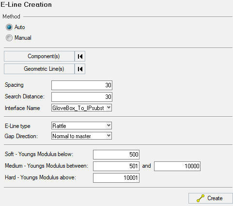
Figure 1.
Figure 1.
You can do the following operations in the panel:
- Components - to select components between which the interface has to be created
- Geometric Lines - to select the geometric line for the selected components
- Spacing and Search Distance- numerical value to define the spacing between the connector placements
- Interface Name - to select and define a name for the interface
- E-Line Type - drop down list to select the required line type. Line
types are -
- Rattle
- Squeak
- Gap Direction - to define the gap direction with respect to master
component. SnRD supports two directions, namely:
- Normal to Master - where the gap direction is perpendicular to master component
- In-plane to Master - where the gap direction is not perpendicular, or is in plane to master component
- Define the Contact Types based on the Youngs' Modulus.
- Create - after making the necessary selections, you can click Create. This will create the connector locations in the model