SS-T: 2020 Spot Welds
Create spot welds in SimSolid.
Purpose
SimSolid performs meshless structural
analysis that works on full featured parts and assemblies, is tolerant of
geometric imperfections, and runs in seconds to minutes. In this tutorial,
you will do the following:
- Create spot welds using a CSV file or spots on lines.
- Create standalone spots.
- Show, edit, hide, and delete spots.
- Solve an analysis with spot welds and review spot weld forces.
Model Description
The following model files are needed for this tutorial:
- 3_plates.x_b
- Spots.csv
- Spots.ssp
Import Geometry
-
Click the
 (Import from file) icon.
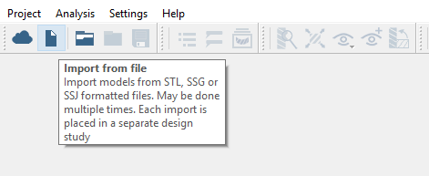
Figure 1.
Import Welds from CSV
Import spot weld locations from an external .csv file.
-
In the Connections workbench toolbar, click the
 (Create spot or laser welds) icon.
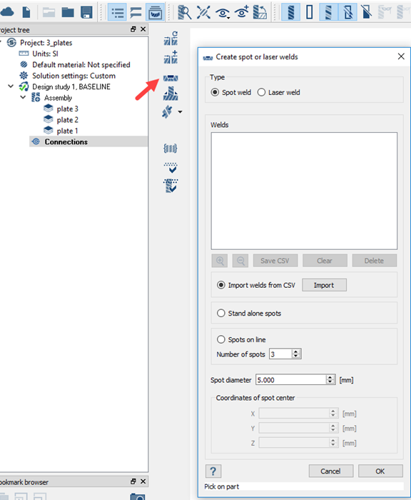
Figure 2. -
Click Open.
Figure 3 shows how the file looks:
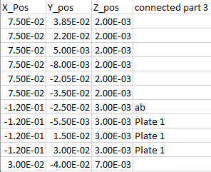
Figure 3.Tip: If more than 2 parts need to be connected, enter alpha numeric value in the "connected part 3" column.The imported welds are listed in the dialog. Welds will fail if the spot's XYZ values lie outside of the tolerance-spot diameter. Failed welds will appear in red.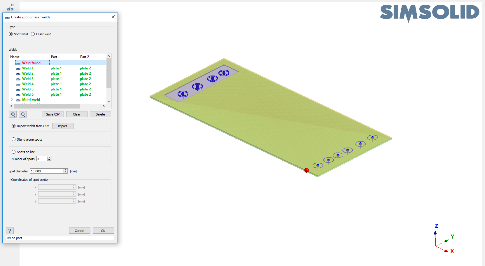
Figure 4. - Optional:
Use the
 and
and  (Zoom in/out) buttons to review welds.
-
Click OK.
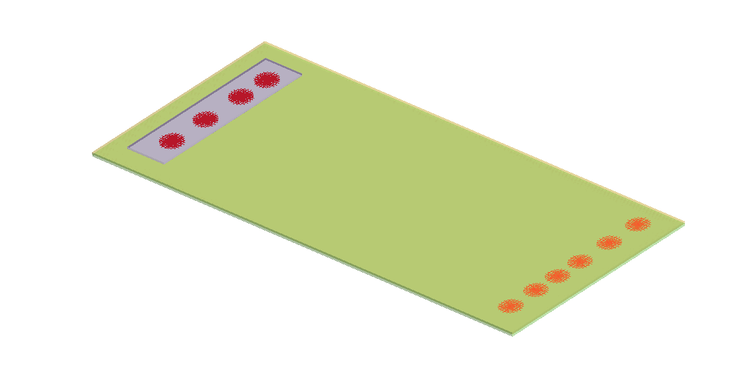
Figure 5.
Create Spot Welds on Line
Create a series of spot welds along a line or polyline.
-
In the Connections workbench toolbar, click the (Create spot or laser welds) icon.
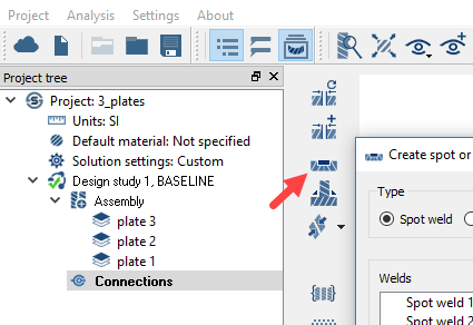
Figure 6. -
Use the up/down arrows to define the Number of
spots.
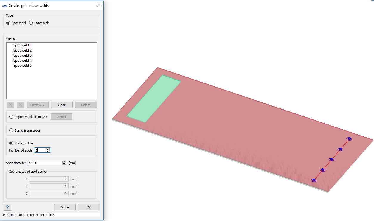
Figure 7.
Create Standalone Spot Weld
Create standalone spot welds at selected points.
-
In the Connections workbench toolbar, click the (Create spot or laser welds) icon.
Figure 8. -
Click on the parts shown in Figure 9 to create spots at desired locations.
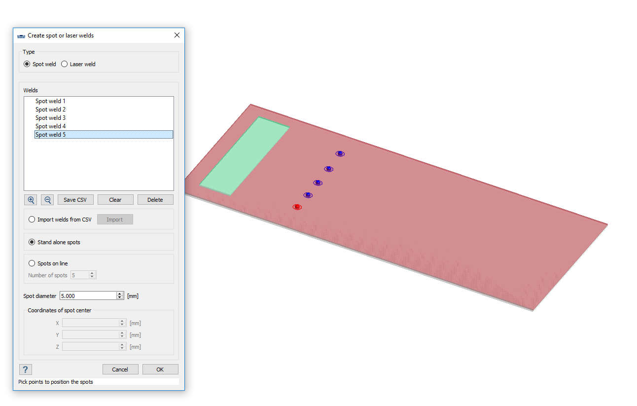
Figure 9.
Edit Spot Welds
Change the diameter of existing spots.
-
In the Project Tree, right-click on Spot
weld 1 and select Edit connection from
the context menu.
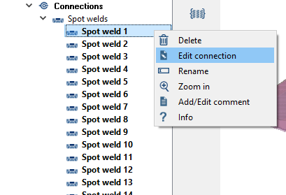
Figure 10. -
Change the diameter to 5.000
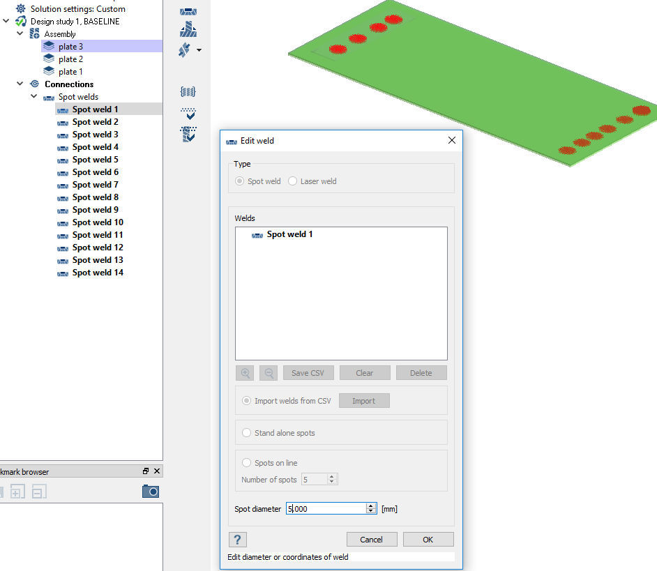 Figure 11.
Open Project
Open the SimSolid project file.
-
Click the
 (Open Project) icon.
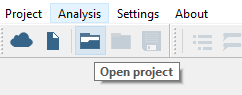
Figure 12.
Review Spot Weld Forces
Solve Structural 1 subcase and review spot weld forces.
-
Click
 (Solve).
-
Review the model and the spot welds created.
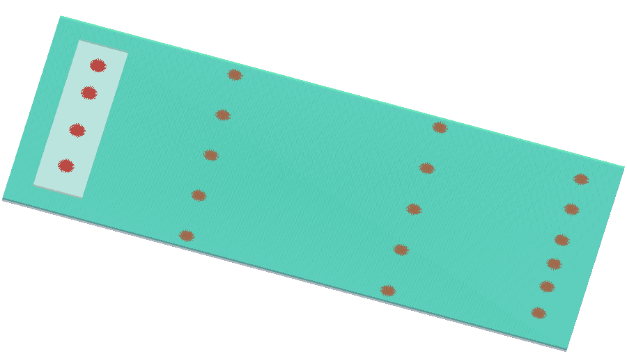
Figure 13. -
Review spot weld forces.
-
On the Analysis Workbench toolbar, select
 (Spot weld forces).
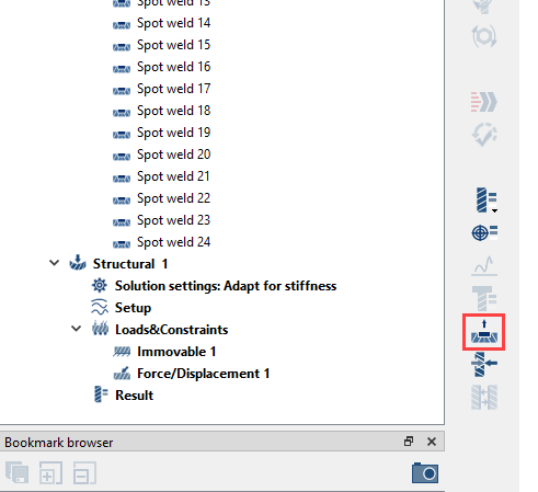
Figure 14.Spot weld reaction forces are listed in the dialogue.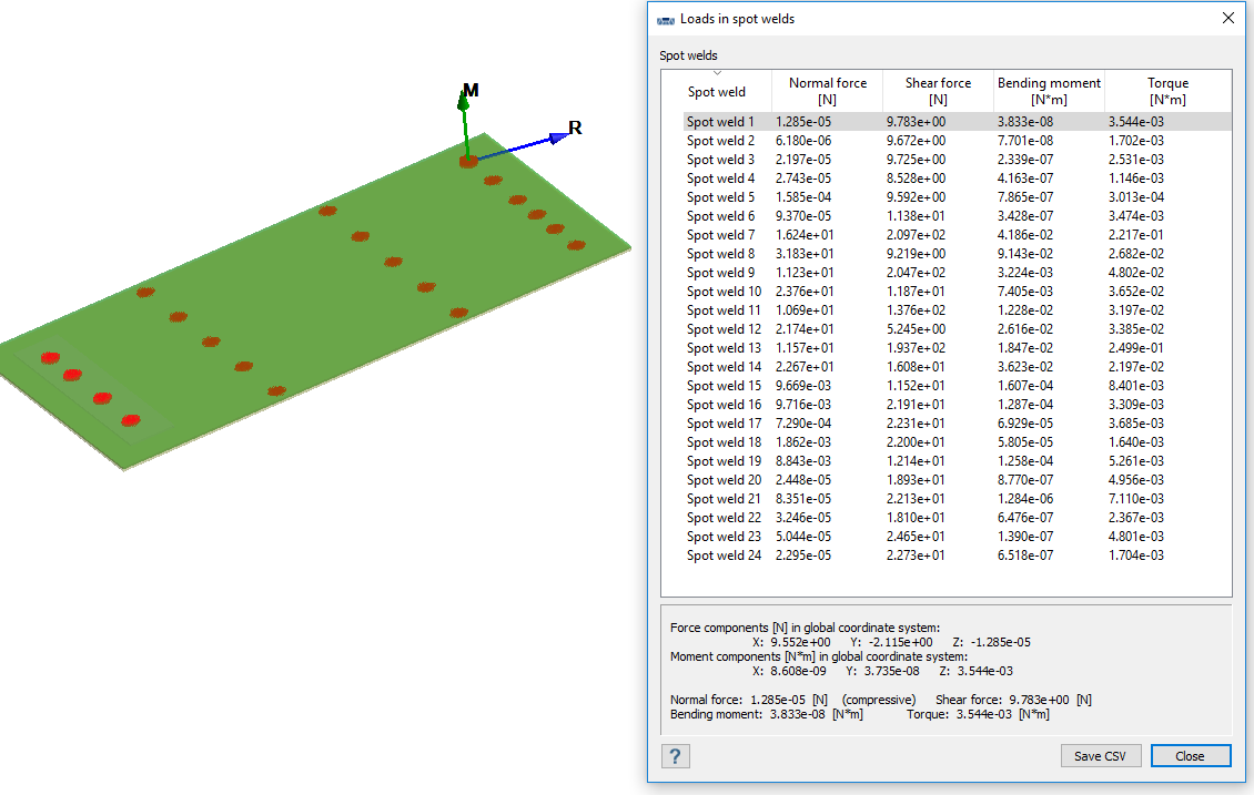
Figure 15.
-
On the Analysis Workbench toolbar, select